7706LT
Extended L-Band RF Fiber Transmitter
Revision 1.1
Page - 13
6.
DOT-MATRIX DISPLAY
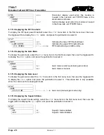
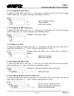
Signal and status monitoring and control of the card’s parameters are provided via the four-digit
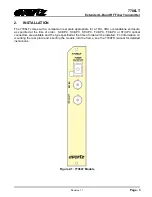
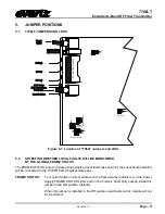
alphanumeric display located on the card edge. The card-edge toggle-switch (see Figure 5-1) is used
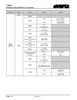
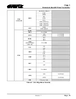
to navigate through the display menus and the push button is used to select options. Table 6-1 provides
a quick reference to the display menu structure.
CTRL
menu items have user-adjustable configuration values associated with them.
STAT
menu items
display operating conditions or configuration values, but do not allow adjustment.
If a specific menu selection has a configuration value associated with it, then this may be changed
using the toggle switch. Pressing the pushbutton will apply the displayed value and return you to the
previous menu level.
The most recent user selection will be maintained in non-volatile memory in the event of power
loss to the module.


