background image


7706LT Series 

Extended L-Band Fiber Transmitter 

USER MANUAL 


© Copyright 2013 - 2016 
 

EVERTZ MICROSYSTEMS LTD. 

5292 John Lucas Drive 
Burlington, Ontario 
Canada L7L 5Z9 
 
Phone: 

905-335-3700 

Sales: 

[email protected]


Fax:  905-335-3573 

Tech Support: 

[email protected]


Fax:  905-335-7571 

Web Page: 

www.evertz.com


Version 1.1, September 2016


The material contained in this manual consists of information that is the property of Evertz Microsystems and is intended solely for the use of 
purchasers of the 7706LT series product. Evertz Microsystems expressly prohibits the use of this manual for any purpose other than the operation 
of the 7706LT series product. Due to on going research and development, features and specifications in this manual are subject to change without 
notice. 
 
All rights reserved. No part of this publication may be reproduced without the express written permission of Evertz Microsystems Ltd. Copies of 
this manual can be ordered from your Evertz dealer or from Evertz Microsystems. 


Содержание 7706LT 27

Страница 1: ... the property of Evertz Microsystems and is intended solely for the use of purchasers of the 7706LT series product Evertz Microsystems expressly prohibits the use of this manual for any purpose other than the operation of the 7706LT series product Due to on going research and development features and specifications in this manual are subject to change without notice All rights reserved No part of ...

Страница 2: ...This page left intentionally blank ...

Страница 3: ...ird grounding prong The wide blade or the third prong is provided for your safety If the provided plug does not fit into your outlet consult an electrician for replacement of the obsolete outlet Protect the power cord from being walked on or pinched particularly at plugs convenience receptacles and the point where they exit from the apparatus Only use attachments accessories specified by the manuf...

Страница 4: ... Class A digital device pursuant to Part 15 of the FCC Rules These limits are designed to provide reasonable protection against harmful interference when the equipment is operated in a commercial environment This equipment generates uses and can radiate radio frequency energy and if not installed and used in accordance with the instruction manual may cause harmful interference to radio communicati...

Страница 5: ... 1 7706LT JUMPERS AND LEDS 11 5 2 SELECTING WHETHER LOCAL FAULTS WILL BE MONITORED BY THE GLOBAL FRAME STATUS 11 5 3 CONFIGURING THE MODULE FOR FIRMWARE UPGRADES 12 5 4 FACTORY AND BDM JUMPERS 12 6 DOT MATRIX DISPLAY 13 6 1 7706LT CONTROLLED PARAMETERS 16 6 1 1 Adjusting the RF Input Power Alarm 16 6 1 2 Selecting the Input Gain Mode 16 6 1 3 Enabling Disabling Squelch Mode 17 6 1 4 Adjusting the ...

Страница 6: ...6 1 20 Displaying the LNB Current 21 6 1 21 Displaying the LNB Current Threshold Level 21 6 1 22 Displaying the Firmware Version 22 FIGURES Figure 1 1 7706LT Block Diagram 1 Figure 2 1 7706LT Module 3 Figure 2 2 Reproduction of 7706LT Certification and Identification Label for Models that are Class 1 Laser Products 5 Figure 2 3 Reproduction of 7706LT Certification and Identification Label for Mode...

Страница 7: ...r implied The only warranty offered by Evertz in relation to this product is the Evertz standard limited warranty stated in the sales contract or order confirmation form Although every attempt has been made to accurately describe the features installation and operation of this product in this manual no warranty is granted nor liability assumed in relation to any errors or omissions unless specific...

Страница 8: ...7706LT Extended L Band RF Fiber Transmitter Page iv Revision 1 1 This page left intentionally blank ...

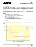
Страница 9: ...provided Features Extended frequency response for L Band signals Protocol independent design transports all modulation formats LNB power with selectable 13 17V DC LNB current limit short circuit protection 22kHz tone on off for LNB local oscillator control RF monitor output for signal peaking and signal distribution Manual gain and AGC modes for tuning optimal CNR performance Fiber link provides e...

Страница 10: ...7706LT Extended L Band RF Fiber Transmitter Page 2 Revision 1 1 This page left intentionally blank ...

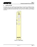
Страница 11: ...r standalone enclosure as specified at the time of order SC UPC SC APC ST UPC FC UPC FC APC or ST UPC optical connectors are available and the type specified at the time of order will be installed For information on mounting the rear plate and inserting the module into the frame see the 7700FR manual for detailed instructions Figure 2 1 7706LT Module ...

Страница 12: ...s connector can also provide LNB power and 22 kHz tone back to the LNB RF OUT Output connector provides a buffered copy of the incoming RF signal for monitoring purposes signal peaking etc or coaxial distribution Although not essential if this connector is to remain unused it is recommended that it be terminated with an appropriate 75 Ohm or 50 Ohm load The RF input is protected to the same degree...

Страница 13: ...product to place the label it is reproduced here in the manuals There is no date of manufacture on this label as it can be traced by bar code label placed on the PCB of each Evertz plug in product Class 1 Laser Products Model number is one of 7706LT or 7706LTxx xx 27 29 31 33 35 37 43 45 47 49 51 53 55 57 59 61 Class 1M Laser Products Model number is one of 7706LTDxxx Dxxx represents ITU Grid Chan...

Страница 14: ...before making a connection The transmission characteristics of the fiber are dependent on the shape of the optical core and therefore care must be taken to prevent fiber damage due to heavy objects or abrupt fiber bending Evertz recommends that the user maintain a minimum bending radius of 5 cm to avoid fiber bending loss that will decrease the maximum attainable distance of the fiber cable Evertz...

Страница 15: ...ted LO Control 22kHz on off selectable 3 2 RF MONITOR OUTPUT Number of Outputs 1 Connector BNC per IEC 61169 8 Annex A F Type and SMA Optional Output Impedance 75Ω 50Ω Optional Return Loss 15dB 10dB for 50Ω Frequency Range 850MHz to 2250MHz Output Level within 2 0dB of input signal 3 3 OPTICAL OUTPUT Number of Outputs 1 Connector Female FC UPC ST UPC FC UPC SC APC FC APC Operating Wavelength Stand...

Страница 16: ...ded L Band RF Fiber Transmitter Page 8 Revision 1 1 3 7 COMPLIANCE Laser Safety Class 1 laser product Complies with 24 CFR 1040 10 and 1040 11 IEC 60825 1 EMI RFI Complies with FCC Part 15 Class A EU EMC directive ...

Страница 17: ...f the input RF signal LNB and AGC mode signals RF HIGH This red LED will be on when the input RF signal is higher than the RF high threshold setting RF OK This green LED will be on when the input RF signal is within threshold settings RF LOW This yellow LED will be on when the input RF signal is lower than the RF low threshold setting GAIN MODE This LED is on when AGC mode is enabled and off when ...

Страница 18: ...put Power is less the upper threshold setting and greater then the lower threshold setting OFF RF Input Power is less then the lower threshold setting or greater then the upper threshold setting 3 YELLOW RF Input Power less then or equal to the lower threshold setting OFF RF Input Power greater then the lower threshold setting 4 RED AGC is on but unable to maintain output power setting GREEN AGC i...

Страница 19: ...s and LEDs 5 2 SELECTING WHETHER LOCAL FAULTS WILL BE MONITORED BY THE GLOBAL FRAME STATUS The FRAME STATUS jumper J3 determines whether local faults as shown by the Local Fault indicator will be connected to the 7700FR frame s global status bus FRAME STATUS To monitor faults on this module with the frame status indicators on the Power Supply FRAME STATUS LEDs and on the Frame s Fault Tally output...

Страница 20: ...ing done to the module For normal operation it should be installed in the RUN position See the Upgrading Firmware section of this manual for more information 5 4 FACTORY AND BDM JUMPERS When shipped from the Evertz facility the FACTORY and BDM jumpers will not be installed These jumpers should not be installed for any reason If jumpers are on these positions they should be removed ...

Страница 21: ... 6 1 provides a quick reference to the display menu structure CTRL menu items have user adjustable configuration values associated with them STAT menu items display operating conditions or configuration values but do not allow adjustment If a specific menu selection has a configuration value associated with it then this may be changed using the toggle switch Pressing the pushbutton will apply the ...

Страница 22: ...AN default SQL ON OFF default SQTH 0 to 60dBm Default 60dBm GAIN visible in manual mode only 0 to 31 5dB Default 0dB OUTL visible in AGC mode only 0 to 50dBm Default 20dBm PSWD 0 to 9999 Default 7154 This area visible only if correct password entered PSWL 0000 9999 LASR ON OFF LNBV 18V 13V OFF Default 22KT ON OFF Default also can only be off if LNBV is off LNTH LWR 0 to 500mA Default 0 UPPR 0 to 5...

Страница 23: ...only 22KT LNB only LNBC LNB only DISP HORZ VERT default STAT BACK PWR 0 to 60dBm RFTH LWR 0 to 60 dBm UPPR 0 to 60 dBm MODE AGC MAN GAIN visible in manual mode only 10 to 30dB SQL ON OFF LASR OK OFF FALT LNBV 18V 13V OFF 22KT ON OFF LNBC 0 to 500mA LNTH LWR 0 to 500mA UPPR 0 to 500mA VER Firmware version Table 6 1 Card Edge Menu Structure ...

Страница 24: ...ult 60 dBm RFTH LWR 0 to 60 dBm CTRL 0 to 60 dBm Upper RF power alarm threshold default 0dBm RFTH UPPR 0 to 60 dBm The 7706LT will not allow threshold settings where the lower threshold is greater than the upper threshold 6 1 2 Selecting the Input Gain Mode The 7706LT has two gain modes available Manual gain mode allows the user to select a fixed gain level for the RF signal AGC automatic gain con...

Страница 25: ...first menu level then use the toggle switch to display SQTH option and press the pushbutton to select it CTRL 0 to 60 dBm RF Squelch threshold range default 60 dBm SQTH 0 to 60 dBm 6 1 5 Adjusting the RF Gain The 7706LT can apply gain to adjust the level of the input signal in 0 5 dB increments This allows weaker signals to be gained up for optimal laser depth of modulation and CNR performance For...

Страница 26: ...ote that this menu item is only applicable and visible when the card is set to operate in AGC mode 6 1 7 Setting the Passcode DWDM versions only Due to the high powered lasers used on the DWDM version of these cards it is possible to turn the laser on and off and protect this function with a passcode This provides added optical safety Depress the pushbutton and select the PSWD option Actuate the t...

Страница 27: ...RL LWR Lower RF threshold level UPPR Upper RF threshold level 0 to 500A RF threshold range LNTH LWR UPPR 0 to 500A 6 1 11 Default Card Edge Display This allows configuration of which operating condition will be displayed as the top level item on the dot matrix display The default is NORM which displays OK or LASER FAULT in the event of a problem with the laser To choose an alternate parameter sele...

Страница 28: ...e Gain Mode To display the gain mode select the STAT menu item in the first menu level then use the toggle switch to display the MODE option and press the pushbutton to select it STAT AGC Gain mode is AGC automatic gain control MAN Gain mode is manual MODE AGC MAN 6 1 15 Displaying the Gain Level To display the gain level select the STAT menu item in the first menu level then use the toggle switch...

Страница 29: ... menu level then use the toggle switch to display the 22KT option and press the pushbutton to select it STAT Indicates whether the 22KHz tone on LNB output is enabled or disabled ON 22KHz tone is enabled OFF 22KHz tone is disabled 22KT ON OFF 6 1 20 Displaying the LNB Current To display the LNB Current select the STAT menu item in the first menu level then use the toggle switch to display the LNBC...

Страница 30: ...ying the Firmware Version To display the firmware version select the STAT menu item in the first menu level then use the toggle switch to display the VER option and press the pushbutton to select it The firmware version will scroll across the display For example VER 1 0 BUILD 006 ...

Отзывы: