background image

39 


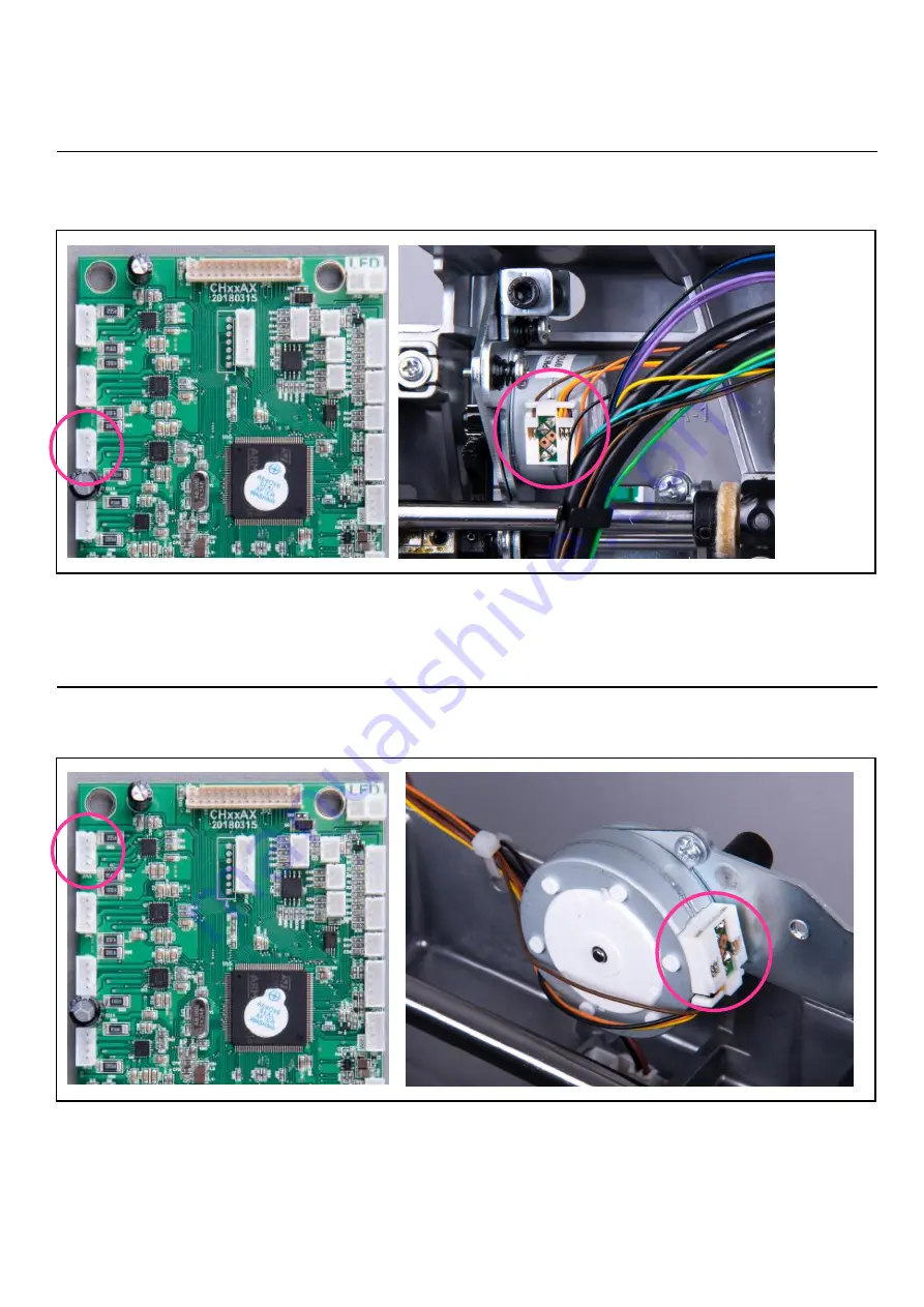
6-3. Trouble shooting 

– Stepping motor(stitch length) 

6-3-1    Check if the cable of the stepping motor is connected to the correct connector on the main board. 

6-3-2    If the problem still exists, please replace a new stepping motor. 

6-4. Trouble shooting 

– Stepping motor(upper tension) 

6-4-1    Check if the cable of the stepping motor is connected to the correct connector on the main board. 

6-4-2    If the problem still exists, please replace a new stepping motor. 

Содержание CH04AX

Страница 1: ...REPAIR MANUAL CH04AX...

Страница 2: ...le and hook 2 3 12 Adjust the play for the rotary hook plates 2 3 13 Adjust the height of the feed dog 2 3 14 Adjust the feed dog position 2 3 15 Adjust the upper thread tension 2 3 16 Adjust the bobb...

Страница 3: ...ttonhole Sewing Failure 2 6 12 Foot Controller Failure 2 6 13 LED Light Failure 2 6 14 Organize the cables 2 7 Embroidery Unit 2 7 1 Main parts of the embroidery unit 2 7 2 Dissemble the embroidery un...

Страница 4: ...page 18 4 031CAA0010 Feed dog gauge 0 9 1 05mm For adjusting the height of feed dog see page 25 5 031V8D0301 Presser bar Gauge 6 0 6 5mm For adjusting the height of presser foot see page 10 6 031CAA0...

Страница 5: ...d Type Item Description Specs Remark 1 Hexagon screwdriver 1 5mm 2 Hexagon screwdriver 2 0mm 3 Hexagon screwdriver 2 5mm 4 Hexagon screwdriver 3 0mm 5 Hexagon screwdriver 4 0mm 6 L shape slotted screw...

Страница 6: ...ssory box 2 1 1 Grasp the accessory box then pull toward by the arrow direction to remove it 2 2 Remove face plate 2 2 1 Use Philips head screwdriver to remove the setscrews of the face plate free arm...

Страница 7: ...4 2 3 Remove Front cover 2 3 1 Use Philips screwdriver to remove the front cover 2 3 2 Remove the harness WIFI module cable...

Страница 8: ...r to remove the back cover Please lower the presser foot lever first 2 4 2 When removing the back cover please pay attention to avoid hitting the receptacle holder and break it 2 5 Remove bed cover 2...

Страница 9: ...ts adjustment 3 1 Play of the Arm shaft Please remove face plate free arm cover free arm base cover base cover front cover in advance Use 2 5mm hexagon screwdriver to loosen 2 setscrews on arm shaft c...

Страница 10: ...3 1 2 to pull the hand wheel outward and turn the hand wheel to move the needle to three different positions highest lowest center Then check if the play of the arm shaft is sufficient 3 1 4 Check if...

Страница 11: ...to check the noise location 3 2 2 Loosen the screw M4X8A as shown in area Check and adjust the tightness of thread take up lever supporter 3 2 3 If it is set too tightly the hand wheel will be difficu...

Страница 12: ...ch pattern 3 3 2 Loosen the 2 0mm hex socket setscrew as shown in area 3 3 3 Pull the needle bar supporter backward to move the needle forward and vice versa as shown in area 3 3 4 Adjust the needle p...

Страница 13: ...ot Remove the face plate 3 4 1 Drop down the feed dog 3 4 2 Raise the presser foot lifter 3 4 3 Use a 2 0mm hexagon screwdriver to loosen the setscrew as shown in area 3 4 4 Put the gauge with the sma...

Страница 14: ...e the gauge to check the height of the presser foot By the smaller side the gauge can be put beneath the presser foot 3 4 9 On the contrary the taller side of the gauge cannot be put beneath presser b...

Страница 15: ...the vertical distance between the needle tip and the needle plate should be between 6 0 6 5mm 3 5 3 If the vertical distance is less than 6mm loosen the screw M4 8A on the rotary sensor collar first a...

Страница 16: ...n area 3 6 3 Turn setscrew as the picture shown below to adjust the needle bar position as shown in area Turn the setscrew in clockwise direction will make the needle position go left Turn it in count...

Страница 17: ...r to loosen the setscrew of threader stopper 3 7 4 Move the threader stopper upward to make the threader hook go up 3 7 5 Move threader stopper in another direction to make the threader hook go down 3...

Страница 18: ...r is not skewed 3 8 Adjust the needle bar height 3 8 1 Remove the face plate 3 8 2 Move the needle to its center position 3 8 3 Use a flathead screwdriver to remove the needle plate 3 8 4 Press the sh...

Страница 19: ...e hand wheel to let needle go to its lowest position 3 8 8 When the needle is at lowest position the gauge will slightly touch the inner brink of the shuttle hook holder 3 8 8 If the needle bar height...

Страница 20: ...ch pattern and set the stitch width to 7mm 3 9 3 Turn the hand wheel to move the needle to the left side and down to its lowest location 3 9 4 Install the timing gauge 3 5mm and its holder then tighte...

Страница 21: ...go down until the tip of shuttle hook holder meets the needle from the front view but not physical touch At this point the distance between the shuttle hook tip and the needle eye should be between 0...

Страница 22: ...or adjustment 3 9 12 After adjusting to the right position tighten the setscrews on the lower shaft gear 3 10 Adjust the distance between needle and hook 3 10 1 Remove the face plate 3 10 2 Choose the...

Страница 23: ...2 0mm hex screwdriver to loosen the hex socket screw for the needle bar supporter pin 3 10 7 Push the needle bar supporter backward and the play will become larger Push it in another direction will ma...

Страница 24: ...lower shaft bias bushing up will increase the play and move it down will reduce the play 3 11 6 While adjusting the correct play please notice that the movable distance for the shuttle hook holder sh...

Страница 25: ...case touch the rotary hook holder plate 2 and form a gap between the rotary hook holder plate 1 3 12 3 The side with 0 3mm can pass the gap but another side 0 5mm cannot pass 3 12 4 Remove the free ar...

Страница 26: ...k holder plate 2 The side with 0 6mm can pass the gap but another side 1 0mm cannot pass 3 12 8 play is out of the standard loosen 2 setscrews for the rotary hook holder plate 2 and adjust its locatio...

Страница 27: ...set the stitch length to 5 0mm 3 13 4 Lay down the sewing machine 3 13 5 Turn the hand wheel to make sure the Phillips screw driver can reach the screw M4 8A as shown below and loosen it 3 13 6 Adjus...

Страница 28: ...uge on the needle plate with the side marked 0 9mm down then turn the hand wheel to make the feed dog move Feed dog should not pass the gauge gap during the movement 3 13 12 Place by the other side 1...

Страница 29: ...le 3 14 4 Tighten 2 setscrews back 3 15 Adjust the upper thread tension 3 15 1 Remove the face plate free arm cover free arm base cover bed cover and front cover 3 15 2 Turn on the machine to set the...

Страница 30: ...eck the tension strength to see if it fits the standard 60 70gf 3 16 Adjust the bobbin case tension 3 16 1 Use a flathead screwdriver to remove the needle plate 3 16 2 Take out the bobbin case 3 16 3...

Страница 31: ...check the tension strength fits to the standard 13 17gf 3 17 Adjust motor belt 3 17 1 Use a belt tension gauge to check the belt tension When press down on the belt for 4 6mm the tension strength sho...

Страница 32: ...sewing stitch forms poorly as below picture adjust 4 0mm hex socket screw in clockwise direction 3 19 BH BH adjustment 3 19 1 Use a Phillips screwdriver to remove the face cover 3 19 2 Check if the o...

Страница 33: ...t position 3 20 2 Place a spool of sewing thread in the spool holder 3 20 3 Follow the instruction to guide the thread through the thread guide 3 20 4 Follow the instruction to further guide the threa...

Страница 34: ...winder thread guide in counter clockwise direction 3 20 8 On the contrary if the upper part of bobbin thread is winder thicker as the picture shows turn the screw in clockwise direction 3 20 9 Check...

Страница 35: ...adjusting winding the bobbin thread again and check if it fits to the standard 80 full and equally wound 3 20 12 Note After winding the bobbin thread please push the bobbin winder shaft to the left f...

Страница 36: ...ronic Components 1 2 3 4 5 6 1 Stepping motor upper thread tension 2 Stepping motor zigzag 3 BH photo sensor complete 4 Stepping motor trimming 5 Micro switch bobbin thread winding 6 Photo sensor plat...

Страница 37: ...34 7 8 9 10 11 12 13 14 7 LED Light panel 8 Stepping motor stitch length 9 LED Light center 10 Main board 11 HF transformer board 12 DC motor 13 DC jack socket foot controller 14 Receptacle assembly...

Страница 38: ...35 15 16 17 18 16 Wi Fi module CH04AX 15 Speed slider 17 Harness 18 Operation keys PCB...

Страница 39: ...36 5 Printed Circuit Board 5 1 Main board...

Страница 40: ...37 5 2 HF transformer board J1 AC power input J2 Main Board J2 J1...

Страница 41: ...ble is connected with both main board and HF transformer board correctly 6 2 DC Trouble shooting Motor 6 2 1 Check if the cable is connected with both main board and HF transformer board correctly 6 2...

Страница 42: ...ect connector on the main board 6 3 2 If the problem still exists please replace a new stepping motor 6 4 Trouble shooting Stepping motor upper tension 6 4 1 Check if the cable of the stepping motor i...

Страница 43: ...correct connector on the main board 6 5 2 If the problem still exists please replace a new stepping motor 6 6 Trouble shooting Stepping motor zigzag 6 6 1 Check if the cable of the stepping motor is c...

Страница 44: ...oting Wi Fi module CH03AX 6 7 1 Check if the harness is connected with the Wi Fi module and the main board properly 6 7 2 If the problem still exists please replace another Wi Fi module or a new harne...

Страница 45: ...k if all buttons speed slider work properly 6 8 2 Please check if the operation panel board connects with the main board correctly 6 8 3 If above items are working properly please change the main boar...

Страница 46: ...l buttons function well with problem 6 9 2 Please check if the button PCB connects to the operational panel board correctly 6 9 3 If the above are checked and found no problems please replace main boa...

Страница 47: ...e if there is proper space between the micro switch and bobbin winder crank 6 10 3 If no issues can be found in the first step please change the micro switch or the main board to see if the problem ca...

Страница 48: ...ound no issues please change the BH sensor board or the main board to fix the problem 6 12 Foot Controller Failure 6 12 1 Please check if the power socket cables connect with the main board correctly...

Страница 49: ...ze the cables 6 14 2 Use the same technique to organize the wires in C part Be sure to keep the cable tie head facing inside and lace the wires in D part in vertical direction to prevent interfering w...

Страница 50: ...hown in the red circle Keep the cable tie head inside to prevent interfering with outlook covers 6 14 5 Use the cable tie to fix the wires for switch receptacle assembly 6 14 6 For CH03AX model a ferr...

Страница 51: ...of the embroidery unit 3 2 1 4 5 6 8 7 9 1 Handle grip 2 Top cover 3 Vertical shaft under cover 1 4 Vertical shaft cover 5 Body cover 6 Vertical shaft under cover 2 7 Frame fixed position button 8 Y...

Страница 52: ...dery unit 7 2 1 Remove the top cover Use a Philips screw driver to remove the setscrews of the top cover Be sure not to break the harness while removing the top cover Push the top cover to the right a...

Страница 53: ...the vertical shaft under cover 1 7 2 3 Remove the vertical shaft under cover 2 Use a Philips screw driver to remove the setscrews of the vertical shaft under cover 2 7 2 4 Remove the vertical shaft co...

Страница 54: ...roider unit Use the screw driver to remove the setscrews Unplug the D type connector wire NOTE When attach the embroidery unit to the body cover please calibrate the center position again please refer...

Страница 55: ...ush one side of the belt until it touches the other side Belt tension should be set to 500gf contactless sound wave type 21 4N 7 3 2 X axis belt tension adjustment Use the screw driver to loosen the s...

Страница 56: ...side to enlarge the gap Make sure the two gears gently fit together then re tighten the two setscrews 7 3 4 Adjusting the distance of the X axis belt gear Use the screw driver to loosen the two setscr...

Страница 57: ...ard J1 D type connector J2 Harness 10P J3 X axis stepping motor connector J4 X axis photo sensor connector J1 Y axis photo sensor JP1 Converter board connector JP2 Y axis stepping motor connector JP3...

Страница 58: ...r to check if the machine can be started Check if LCD LED displays normally and LED light is on without any problem Either Main board or HF transformer board is damaged Change the main board or HF tra...

Страница 59: ...ssembly for free arm cover 2 Drop feed lever is not properly installed Remove the free arm cover push the drop feed lever to the right side and attach the free arm cover back Push the drop feed lever...

Страница 60: ...to page 28 for adjustment Check the pattern completeness of Buttonhole Refer to page 28 for adjustment 12 Bobbin winder shaft not turning Bad micro switch of bobbin winder Refer to page 45 for adjustm...

Отзывы: