


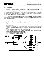


7700 MultiFrame Manual
7707VR-8 8 Channel SDI Fiber Receiver
Revision
1.4
7707VR-8-3
"
Do not hook up the 7707VT-8 DWDM and 7707VR-8 cards directly with a short
fiber optic cable. The 7707VT-8 DWDM card pr7dBm of power,
which will damage the receiver if connected directly.
"
Do not hook up the 7707VT-8 cards that output more than -7dBm of power
(see 7707VT-8 specifications for output power of various laser types) and
7707VR-8-H high sensitivity receiver cards directly with a short fiber optic
cable. The 7707VT-8 cards that produce more than -7dBm of power will
damage the receiver if connected directly.
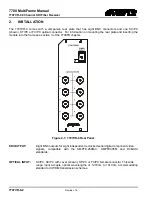
2.1.
HANDLING AND CONNECTING FIBERS
"
Never touch the end face of an optical fiber. Always keep dust caps on optical
fiber connectors when not connected and always remember to properly clean
the optical end face of a connector before making a connection.
The transmission characteristics of the fiber are dependent on the shape of the optical core and therefore
care must be taken to prevent fiber damage due to heavy objects or abrupt fiber bending. Evertz
recommends that you maintain a minimum bending radius of 5 cm to avoid fiber-bending loss that will
decrease the maximum attainable distance of the fiber cable. The Evertz fiber optic modules come with
cable lockout devices to prevent the user from damaging the fiber by installing a module into a slot in the
frame that does not have a suitable I/O module. For further information about care and handling of fiber
optic cable see section 3 of the Fiber Optics System Design section of this manual binder.