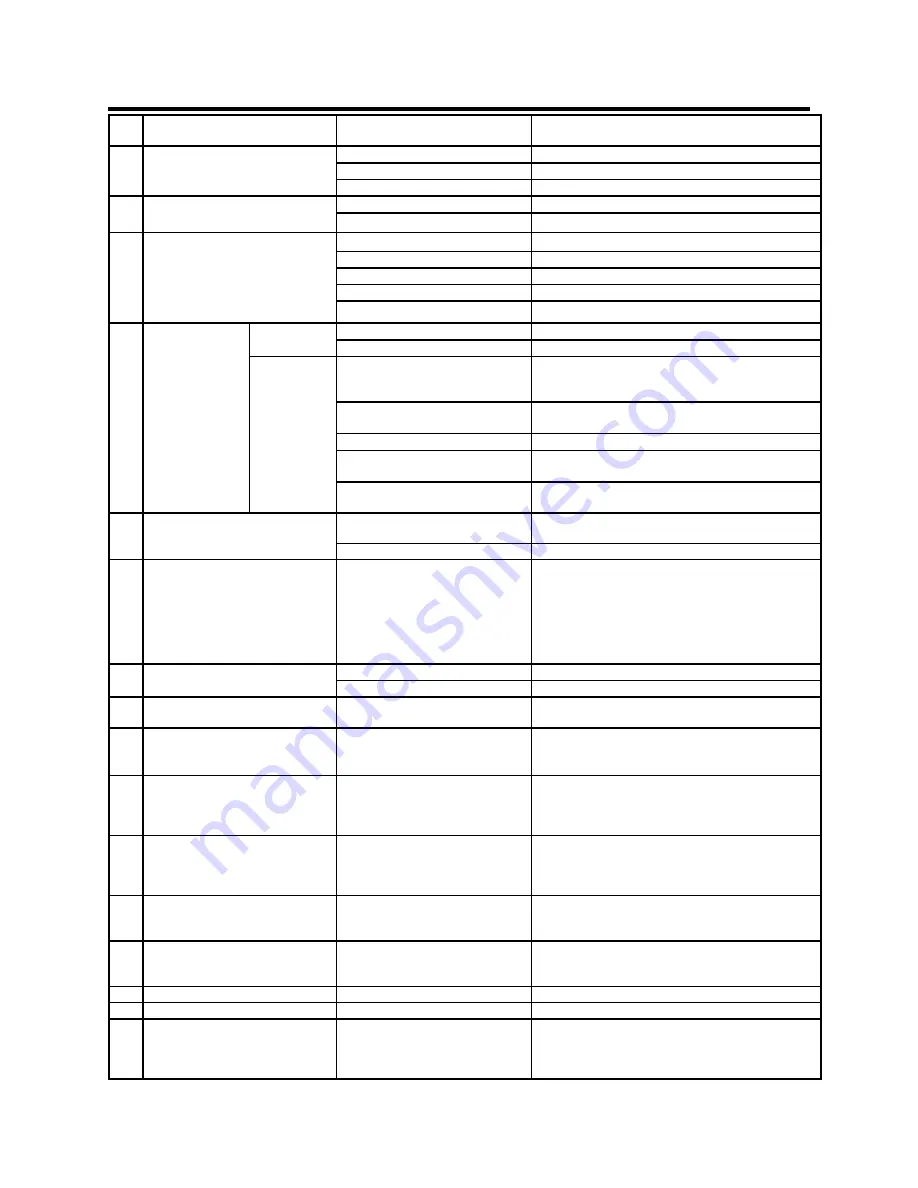
Everlast POWER i-MIG 200 Скачать руководство пользователя страница 32

32 

Section 3 

Trouble Shooting 


NO
.


Trouble


Possible Cause


Solution


1


Unit is switched on, but the power 
light isn

t on


Switch damaged.


Replace.


Unit Fuse damaged.


Replace.


Power breaker tripped.


Reset.


2


After welding machine is over-
heating and the fan does not work


Fan damaged.


Check fan housing and fan.  Replace if necessary.


Fan power connector is loose.


Tighten wires, check for dislodged connectors.


3


When torch switch is pressed, no 
gas Flows 


No gas in the gas cylinder.


Replace.


Gas pipe leaks gas.


Resolve .


Gas solenoid valve damaged.


Check and clean/replace.


Torch switch damaged.


Repair or Replace.


Control board damaged.


Inspect the circuit.


4


Wire

-

feeder does 

not work


Wire reel 
does not turn


Motor damaged/Fuse blown.


Check and Replace.


Control circuit  damaged.


Check the board.


Wire reel 
turns


The tensioner is loose or wire slips 
on rollers. Wrong size drive roll. 
Wire is not mated in drive groove.


Increase tension.  Check for proper drive roll size/type.   
Make sure wire is in groove not riding on top of the 
drive roller shoulder.


The  drive roller doesn

t fit  the 

diameter of weld wire.


Change roller or wire size to match.


Wire Spool is damaged.


Change out wire spool.


Gun liner  is jammed.


Repair or change it, clear wire from liner/clean liner 
with compressed air.


Contact Tip is jammed because of  
slag or burn back.


Clean or replace. If with Aluminum, increase tip size to 
next size.


5


No arc, or no output voltage


Work clamp engaged in wrong  
connector.


Change polarity.


Control circuit damaged.


Check the circuit.


6


Welding stops and warning light is 

on, Wire continues feeding but no 

arc


Self

-

protection has engaged.


Check over

-

voltage, over

-

current, over

-

temperature, 

lower

-

voltage and over

-

temperature. Allow unit to cool 

if over heated.  If an OC, use a shorter wire stick out or 
smaller diameter wire or reduce power settings with 
large diameter wires.  Check power plug  for problems. 
If easily tripped the Resistor value too low. (Contact 
Everlast if OC is tripping regularly with normal settings.)


7


Welding  Voltage/Current is uncon-
trollable


 Potentiometer damaged.


Repair or Replace it.


Control board damaged.


Check the circuit.


9


Intermittent Arc/ Wandering arc


Work Clamp is not secure or it is 
damaged.  Too windy/breezy.


Check and/or Work Clamp, change position of clamp 
and attach direct to the work.  Move out of wind.


10


Excessive spatter


Voltage too high too high arc force/ 
Too high wire speed. Too much 
torch angle. Wrong size nozzle


Lower voltage or increase wire speed.  Check torch 
angle for less than 15° push or pull.  Change arc force 
settings to reduce spatter. Change nozzle size.


11


Weld sooty or oxidized looking


Poor metal prep, poor gas flow, too 
much torch angle, wrong gas type, 
windy or breezy. Plugged nozzle


Thoroughly clean metal, check gas flow and reposition 
gun so gas flow is not creating turbulence.  Move in-
doors if necessary.  Reposition the welder so its fan will 
not blow on the weld area. Clean nozzle.


12


Bird nesting of the wire around the 
drive roll


Jammed gun liner,  wire too soft 
(aluminum), gun hose is kinked or 
coiled too tightly.  Too much ten-
sion / pressure on wire feeder .


Reduce wire feed tension so that drive will slip if it 
encounters too much resistance Check Gun and liner 
and replace if necessary. Straighten cable.


13


Wire feeds irregularly


Wrong drive roller or wrong size 
drive roller, too little tension on 
wire, wire in wrong groove.


Check and match wire size to groove size, increase 
tension on drive rollers.  Check to make sure the wire is 
not riding on the shoulder of the drive roller.


14


Wire burns back and seizes in tip


Wrong contact Tip size or too much 
burn back time set.


Match tip size for wire diameter.  Reduce burn back 
time.  If using with aluminum, use tip designed for 
aluminum or use one size larger tip than the wire.


15


Nozzle arcs to work piece welding


Nozzle plugged with spatter


Check/clean nozzle and use a nozzle dip.


16


In Stick mode will not arc


Cables not connected, inverter issue


Check connections.


17


In Stick mode, the rod sticks


Arc force control is set too low, arc 
striking method is poor, wrong 
polarity, too low of amperage. Wet 
welding rods or wrong kind.


Check polarity. Increase arc force control. Change arc 
striking method. Increase amperage.  Use fresh welding 
rods when possible.


Содержание POWER i-MIG 200

Страница 1: ...755 9353 Specifications and Accessories subject to change without notice 329 Littlefield Ave South San Francisco CA 94080 USA Operator s Manual for the Power i MIG 200 Safety Setup and General Use Guide CC CV mig stick WELDER GMAW smaw SMAW IGBT DC GMAW CC CV 120 240V DV ...

Страница 2: ...ck Operation General Notes Concerning Operation Expanded View of MIG Torch Trouble Shooting 3 4 5 9 9 10 11 12 12 13 14 15 16 18 19 20 21 23 29 30 31 32 NOTE Environment Maintenance and Safety Keep this welder at least 12 inches away from all objects for proper cooling Do not exceed 40 C in environment or duty cycle will be reduced Regularly inspect and clean the welder and circuitry on a quarterl...

Страница 3: ...ct with each other Technical advisors are active on the forum daily We also divide our support into two divisions technical and welding per formance Should you have an issue or question concerning your unit please contact performance technical sup port available through the main company headquarters available in your country This support is free to all Ever last customers For best service call the...

Страница 4: ...in toll free number 1 877 755 WELD 9353 9am 5pm PST M F 11am 4pm PST Sat FAX 1 650 588 8817 Everlast Canada Everlast consumer satisfaction email sales everlastwelders ca Everlast Website everlastwelders ca Everlast Technical Support sales everlastwelders ca Telephone 905 630 8246 9am 4 30pm EST M F 10am 1pm EST Sat FAX 1 905 639 2817 Everlast Australia Sydney 5A Karloo Parade Newport NSW 2106 02 9...

Страница 5: ...afe and proper operation If you feel you need more information please contact Everlast The warranty does not cover improper use maintenance or consumables Accessories such as guns torches regulators foot pedals etc are not covered in the unit warranty They are cov ered under a separate warranty Do not attempt to alter or defeat or otherwise render any piece or part of your unit unserviceable parti...

Страница 6: ...e equipment If no protection is availa ble exclude them from the work area Even brief exposure to the rays from the welding arc can damage unprotected eyes Always wear hearing protection because welding and cutting can be extremely noisy Ear protec tion is necessary to prevent hearing loss Even prolonged low levels of noise has been known to create long term hearing damage Hearing protection also ...

Страница 7: ...tions at all times Any burning of the eyes nose or throat are signs that you need to increase ventilation Stop immediately and relocate work if necessary until adequate ventilation is obtained Stop work completely and seek medical help if irritation and discomfort persists WARNING Do not weld on galvanized steel stainless steel beryllium titanium copper cadmium lead or zinc without proper respirat...

Страница 8: ...p all combustible materials including rags and spare clothing away from area Keep all flammable fuels and liquids stored separately from work area Visually inspect work area when job is completed for the slightest traces of smoke or embers If welding or cutting outside make sure you are in a cleared off area free from dry tender and debris that might start a forest or grass fire Do not weld on tan...

Страница 9: ... Wire roll size and diameter 023 045 with optional drive rolls and contact tips Spools up to 8 in diameter 10 12 lbs Additional Features Burn back control Auto Pre flow Post flow Arc Force control Analog input with Digital Micro controller Spool gun ready Euro Quick connector Stick Function Accessories 15 Series MIG torch 10 ft 3m Work clamp 10 ft 3m 300 A Stick Torch Regulator 240 120V adapter Se...

Страница 10: ...V 110V 10 100A 20 4V 24V 220V 10 160 A 20 4 24 V X 35 60 100 U0 V 60 I2 220V 160 A 130 A 100 A U2 220V 26 4 V 25 2 V 24 V I2 110V 100A 80A 60A U2 110V 24V 23 2V 22 4V 1 50 60 Hz U1 110 220V 110 V I1MAX 33A I1EFF20 A 220 V I1MAX 36 A I1EFF22 A 240 V I1MAX 34 A I1EFF20 A PROTECTION IP21S COOLING METHOD FULL TIME FAN INSULATION F WIRE SPEED FEED RATE 60 600 INCHES PER MINUTE f1 f2 1 S S EVERLAST MIG ...

Страница 11: ...ol gun compatibility to economically expand it s capability for welding aluminum and other expensive metals that lend themselves well to smaller and less costly spools of wire It can also be fitted with optional flux core drive rollers for applications where solid MIG wire is not the best solution 1 3 Installation The basic construction of the Power i MIG is rugged and durable and is considered id...

Страница 12: ...Table 2 WIRE DIAMETER WELDING AMPS A PLATE THICKNESS GAS FLOW RATE MAX 023 0 6 25 110 040 063 1 0 1 6 15 20 CFH 7 10 lpm 030 0 8 35 200 040 128 1 0 3 2 20 25 CFH 10 14 lpm 035 0 9 45 250 040 128 1 0 3 2 20 30 CFH 10 16 lpm 040 1 0 45 250 050 25 1 2 6 0 25 CFH 14 lpm 045 1 2 60 250 25 6 0 25 CFH 14 lpm MIG GMAW CURRENT WIRE SINGLE PASSTHICKNESS GENERAL SUGGESTIONS METAL THICKNESS ELECTRODE SIZE WEL...

Страница 13: ... AND POLARITY MIG WORK MI MIG MIG STICK MIG SPOOL GUN For Flux Core install work in positive and change polarity under the access cover Be sure to use the special serrated drive rollers for Flux Core which are available as an option Contact Everlast to purchase additional drive rolls See next page for instructions on chang ing polarity and drive rollers ...

Страница 14: ...ensioner for future reference 7 Hold torch straight out as possible Press gun trigger to feed wire until the wire exits the end of the torch 8 Adjust tensioner clockwise until drive rolls will not slip when the wire comes into contact with a hard surface and the wire will curl up on end Remember to keep wire away from metal that is attached to the work clamp to prevent the wire from arcing while p...

Страница 15: ...ector 9 Positive Connector Flux Core Work Clamp Stick Torch 8 Negative Connector MIG Work Clamp Stick Work Clamp 7 Control Spool Gun Setup Guide and component Identification Section 2 1 Protective Cover 5 LED Indicators ON TEMP OVERCURRENT 6 Amp Wire Speed Adjustment Knob MIG Wire Speed in min Stick Amps 3 Arc Force Control MIG Stick 11 Adjustment Knob MIG Volts ...

Страница 16: ...cts the drop in voltage experi enced when the arc length is too short and falls below 20 volts The amps are automatically in creased to offset the loss of voltage to maintain the welding arc and prevent the rod from going out and sticking It can also be used to help in crease penetration Too much arc force in stick can or MIG can create a violent arc so be careful about setting too much For MIG a ...

Страница 17: ...r to the negative position 9 Positive Polarity Connector Connect to Stick torch in Stick Mode Connect to work clamp if us ing flux core See comments regarding flux core operation in item 11 10 Euro Quick Connect for MIG This style of connec tion makes the i MIG compatible with many after market MIG torches guns Connect the MIG torch by aligning pins on the gun cable with the recepta cle and pushin...

Страница 18: ...18 3 Burn Back Control Timer Setup Guide and component Identification Section 2 SIDE VIEW POWER i MIG 200 4 Wire Feeder Assy 1 Wire Spool Holder Assy Burn Back 0 1 5 2 Polarity Buss Bar ...

Страница 19: ... energized for a short time after the wire feeder stops feeding The wire will burn back to the de sired length by adjusting the control This im proves re starts and keeps the user from hav ing to re trim the wire between welds NOTE Too much burn back time may cause the wire to burn back to far and seize to the tip 4 Wire Feed Assembly Note the numbers on the side of the tensioner These numbers are...

Страница 20: ...nt Identification Section 2 1 Gas Connector Barb Type REAR VIEW BACK PANEL POWER i MIG 200 4 5 A fuse for Wire Feeder 2 Main Power Switch 3 Power Cord NEMA 6 50 Plug GAS INLET 1x110 220V FUSE 5 Fan Shroud 6 Ground Where required ...

Страница 21: ...ding the clean power rating on specific units Everlast does not pro vide a list of approved generators Manufactur ers rate their units as clean power independent ly according to industry standards The plug is the NEMA 6 50P This is the standard plug for welders operating on 240V in the US and Cana da Other countries will have different configu rations 4 Fuse This fuse controls the wire feeder If i...

Страница 22: ...r too cold For some people it may not even close However nothing can substi tute for watching the arc and listening to the sound of the arc A crisp steady sound frequently re ferred to as a Bacon frying sound should be heard The actual frying sound can vary somewhat and may have somewhat of a high pitch whine to it somewhere between the sound of a flying bee and a mosquito If these sounds are pres...

Страница 23: ...d This is especially help ful when pure CO2 is used 4 The arc force can improve weldability of thinner metals without having to step down a size in wire While ultimately there are limits to what any given wire can weld on the lower end of it s range it does help improve the low amp weld ing characteristics of the wire diameter For the best possible experience welding with the Power i MIG adjust ar...

Страница 24: ...tical position with no more than 5 de grees lean in either side to sidedirection Holding the wire too far off from the metal will result in rough starting and too long of wire stick out Once the arc has been established the gun can then either be pushed or pulled in the direction of the weld In either case the gun nozzle should be posi tioned directly over the weld without angling the wire to one ...

Страница 25: ...erious injury may occur A MIG wire such as ER70S 6 or ER70S 2 includes a sufficient level of deoxidizers such as silicone and copper that are formulated to allow it to handle mi nor to moderate amounts of rust and mill scale These deoxidizers will float out most moderate amounts of contaminates out of the weld and will appear in the usual form of glassy like deposits on top of the cooled metal The...

Страница 26: ...is backer can later be ground or cut off However in many cases a plain open root can be used as a backer plate adds to the time and labor involved A knife edge is also acceptable so long as the joint is fully penetrated when the weld is completed Open root gaps without a backer can range from 1 16 to 1 8 depending upon wire diameter and application 1 4 Fillet 1 4 Fillet s 1 4 V Joint 1 4 Butt Join...

Страница 27: ... weld joint or the other This balances the heat on both sides of the joint and keeps the bead centered Don t confuse this with push or pull angle in the travel direction Correct Technique The gun is angled toward the back of the weld when traveling forward This angle should not exceed 15 degrees This provides a narrower but more deeply pene trating weld Use this method when Flux Core wire is being...

Страница 28: ...age and amperage slow down to fill joint more Use push technique Characteristics Large convex weld with bulging at toes weld legs exceed thickness of the metal being welded Possible Causes Not enough voltage too much wire speed overfilling due to too slow of forward travel speed and or poor weaving technique Remedy Increase voltage increase forward travel speed reduce weaving width Proper Weld Cha...

Страница 29: ...em different One of the main ones is that the arc is better controlled in most situations by pushing in when the arc seems to get weak or unstable and the arc force will kick in as the voltage drops Holding too long of an arc will signal the inverter to shut down and quit weld ing This threshold is shorter than most transformers and an extremely long arc cannot be maintained However with a little ...

Страница 30: ...while welding aluminum in the MIG process you will burn up contact tips almost instantly 5 When using the optional spool gun the amp wire speed control is controlled at the panel Contact Everlast directly to purchase the correct spool gun for this welder 6 Flux Core requires the use of serrated drive rollers These grip the wire and feed it correct ly at a steady speed Flux Core drive rolls are ava...

Страница 31: ...r 1 Remove the securing nut of the liner 17 which exposes the end of the wire guide 2 Straighten the gun cable and withdraw the liner from the gun 3 Carefully push a new wire guide in to the gun Make sure that the wire guide travels all the way to the contact tip 4 Make sure the O ring at the machine end of the gun is installed 5 Tighten the wire guide in place 6 Cut the liner 2mm from the mountin...

Страница 32: ...s uncon trollable Potentiometer damaged Repair or Replace it Control board damaged Check the circuit 9 Intermittent Arc Wandering arc Work Clamp is not secure or it is damaged Too windy breezy Check and or Work Clamp change position of clamp and attach direct to the work Move out of wind 10 Excessive spatter Voltage too high too high arc force Too high wire speed Too much torch angle Wrong size no...

Отзывы: