EverFocus PARAGON264x4 series Скачать руководство пользователя страница 111


104

Connection Procedure: 


The First step is to purchase or make a cross-over cable. We recommend purchasing one if you 

have never made a cross-over cable. Please remember you can not use a straight through network 
cable for this application 


Once you have a cross-over cable plug one end into the LAN port on the back of the DVR and the 

other into the network card on the back of the computer. 


Log into the EverFocus DVR menu and go to the Network Setting Menu.  


You must use the Static IP option for this type of connection. 


Assign an IP of 192.168.001.003, a Subnet Mask of 255.255.255.000, and a Gateway of 
192.168.001.001. You can ignore DNS Server. 


The next step is to set the computer’s network settings to match those of the DVR. You will need 

Administrator privileges on your Windows machine to do this. 


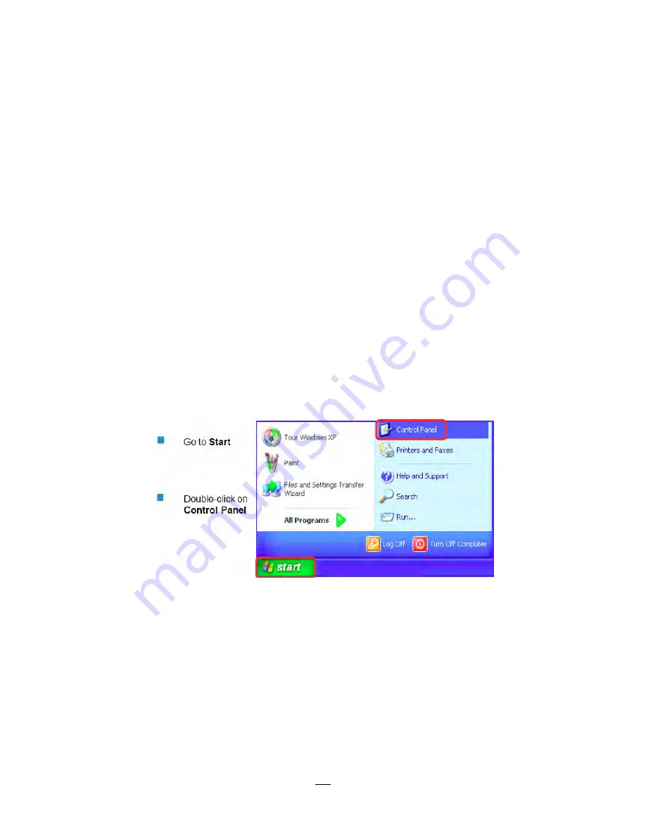
To assign a fixed IP address in Windows 2000/XP.  


Содержание PARAGON264x4 series

Страница 1: ...Instruction Manual P PA AR RA AG GO ON N2 26 64 4x x4 4 3 32 2C CH H S Se er ri ie es s D DV VR R...

Страница 2: ...written permission of the Everfocus Electronics Corporation Release Date June 2011 QuickTime is a registered trademark of the Apple Computer Inc Windows is a registered trademark of the Microsoft Corp...

Страница 3: ...void to power off DVR during playback or recording operation Rack Mount Instructions The following or similar rack mount instructions are included with the installation instructions A Elevated Operati...

Страница 4: ...nt does cause harmful interference to radio or television reception which can be determined by turning the equipment off and on the user is encouraged to try to correct the interference by one of the...

Страница 5: ...INSTALLATION 14 1 11 NETWORK CONNECTION 14 1 11 1 Direct PC Connection through Crossover Network Cable 15 1 11 2 Network Connection through Patch Cable 15 1 12 FINAL INSTALL PROCESS 16 2 MOUSE AND FRO...

Страница 6: ...MENU 39 4 2 EXPRESS 39 4 3 CAMERA SETTING 42 4 3 1 Basic Setting 42 4 3 2 Video Adjust 45 4 3 3 Motion 46 4 3 4 Video Loss 49 4 4 RECORD PLAY SETTING 50 4 4 1 Record 51 4 4 2 Built in Calculator 52 4...

Страница 7: ...NETWORK SETUP 102 5 7 SIMPLE ONE TO ONE CONNECTION 103 5 8 DIRECT HIGH SPEED MODEM CONNECTION 108 5 9 ROUTER OR LAN CONNECTION 110 6 REMOTE OPERATION FROM BROWSER 113 6 1 CONNECTING TO PARAGON 264X4 1...

Страница 8: ...recording settings and network configuration from a single screen Choose from continuous event or schedule recording or pick the number of days you want to record and the Express Setup does the rest V...

Страница 9: ...view desired recordings Express Search Use the intuitive playback bar with simple drag drop operations Smart Search Directly catch the movement in the specified area Snapshot search Show snapshots fr...

Страница 10: ...3 Power cord x 1 Mouse x 1 DVR x 1 User manual x 1...

Страница 11: ...r Outputs HDMI VGA 1080p Call Monitor Output BNC NTSC PAL follows input type Video Matrix Monitor Output BNC x 4 Audio Inputs 16 inputs 16 on RCA socket supplied Line level Audio Outputs 2 x RCA socke...

Страница 12: ...40 C 32 F 104 F 20 80 humidity Certificates CE FCC UL Supported PTZ Protocols EverFocus Pelco D Pelco P Samsung Transparent 1 4 FRONT PANEL Your primary interaction with your new DVR will be through t...

Страница 13: ...LED POWER LED indicating power on HDD1 2 LED indicating HDD1 HDD2 active HDD1 Internal Removable HDDs in DVR HDD2 External HDDs connected by eSATA port LAN LED for network traffic 11 ALARM LED for al...

Страница 14: ...y active in Full screen at Main monitor 18 SEQ Sequence key for automatic switching of a defined camera sequence 19 DISPLAY The DISPLAY key switches titles and status messages on the Screen in 4 steps...

Страница 15: ...4 Video inputs VIDEO IN 1 32 BNC video inputs for 1 Vpp Composite video signals automatic 75 Ohm termination high impedance switching upon loop through output load 5 LAN RJ45 network socket 6 RS232 s...

Страница 16: ...l screen live display sequence mode and alarm camera switching 11 Alarm inputs Alarm inputs for dry contacts programmable NO or NC in alarm menu 12 Audio output 2 x Audio output 13 Alarm outputs 2 x N...

Страница 17: ...er full HD output resolution 1920x1080 progressive 60 Hz vert 68 KHz hor Make sure that the connected monitor s specifications comply with these resolution requirements Please do not exceed the max HD...

Страница 18: ...o record control is done in the Camera 1 16 screen there is no specific camera allocation 1 8 ALARM CONTACTS INSTALLATION The alarm inputs can be used to start recording or for recording rate adjustme...

Страница 19: ...s A shielded cable should be used if the installed cables are expected to be highly susceptible to interference The number of devices installed in one bus is limited to 32 and the maximum cable length...

Страница 20: ...nables the additional connection of 31 further devices to each output the output itself represents one device The maximum system expandability depends on the RS 485 address range of the installed devi...

Страница 21: ...al telemetry control is provided by USB mouse control or by the optional EKB 500 keyboard Supported protocols EverFocus Pelco D Pelco P Samsung Transparent Required DVR settings RS 485 receiver addres...

Страница 22: ...on to a single PC Make sure that the PC is equipped with a 10 100Mbps compatible network connection Figure 1 3 Direct PC Connection Pinout of crossover cable 1 11 2 Network Connection through Patch Ca...

Страница 23: ...SS Once you have completed the basic wiring connections you are ready to turn on the DVR Simply plug in the power source The POWER LED will light up if power is normal Once the system has finished loa...

Страница 24: ...elected screen will be highlighted by a white frame 2 Double clicking on a channel screen will display full screen for this channel 3 To enable audio out click the audio icon ex at lower side of the s...

Страница 25: ...on a choice to select it 3 In section 3 all the options for the selected choice will be available Click on a field to make changes 2 1 4 Field Input Options The following are examples of different typ...

Страница 26: ...r Right Note about on screen keyboard Click on a button to input that character The buttons on the right and bottom have the following functions Space Enter a space Caps Switch to capital letters Dele...

Страница 27: ...icon to perform that action These actions are covered in detail in Chapter 3 3 Press Menu to close the DVR menu bar 2 2 3 Front Panel Key Review The basic principle of front panel operation is to use...

Страница 28: ...r to make changes Note press Menu button to go back to the previous menu section 2 2 5 Field Input Options Textbox Press Enter key and an on screen keyboard will appear see note about on screen keyboa...

Страница 29: ...nter key on the front panel to input the selected characters When finished highlight and press the Enter key on the front panel to confirm The buttons on the right and bottom have the following functi...

Страница 30: ...32CH options users may be asked to log in for authority identification To log in follow these steps 1 Right click on the screen or press the Menu Key to display the Main Menu 2 Choose or click or pre...

Страница 31: ...lick the screen the image will show a white frame on screen if the camera has been selected When in quad display mode press the quad layout icon in layout menu to select all four cameras Front panel U...

Страница 32: ...ar to the select time to playback The start time and end time for time bar appears below the bar The status of each camera is represented by different colors on the time bar Green means normal orange...

Страница 33: ...reset position if supported by the camera a Move PTZ camera to the specified position b Click Preset button c Click the number of the desired position This will be displayed in the box d Click Set but...

Страница 34: ...t respond until you EXIT the PTZ mode 3 6 2 Express Control of PTZ If the PTZ control panel menu has first been opened and then hidden the mouse can be used to control basic PTZ functions Quick Mouse...

Страница 35: ...TZ pan tilt right and down 6 Focus closer 10 Focus further 7 Zoom in 11 Zoom out REMEMBER Click X at the top right corner to hide the PTZ menu see Express control below Click Exit to leave PTZ functio...

Страница 36: ...lected channel to put that camera in full screen mode By front panel Press any channel key to bring that channel to full screen mode With a mouse double left click again on the screen to return to the...

Страница 37: ...ecording Playback Fast forward Fast backward Back pause Alarm Motion Video loss Express copy Audio out 3 Press again to show status information Please see the following table for status representation...

Страница 38: ...e arrow keys to bring a different portion of the magnified image into view Users can control the portion of the magnified image to be displayed by clicking directly on screen Figure 3 4 Zoom Express C...

Страница 39: ...Figure 3 5 Search Menu Time Search Play From Select the time to begin the search by choosing the Date and Time Click on the Play button to start the search The DVR will automatically begin to play th...

Страница 40: ...ect which cameras to include in the search Event Select which event type s to search for Choose from Alarm Motion or Video Loss Click on the Search button to start searching The search results will be...

Страница 41: ...ect ending date Time Select ending time Camera Select which cameras to review Grid Setting Press Grid Setting button to open the motion grid setup window Edit Motion Grid Press this button to edit the...

Страница 42: ...rid Setting to launch motion grid setting page 2 Use Jog Shuttle to scroll above or below list of buttons to enter the grid setting area 3 Press Enter key to display grid 4 Use Jog to move up down and...

Страница 43: ...e Go to next page Play Playback selected item Copy Copy selected item 3 12 4 Snapshot Search Snapshot Search shows snapshots of the specified interval it helps users to quickly find the interested sce...

Страница 44: ...val next to the first thumbnail and so on If forward is selected as search direction a white frame will surround the selected snapshot at the first thumbnail If backward is selected the search date ti...

Страница 45: ...to be archived Copy To Select whether you want to copy to USB or DVD Data Size Shows the estimated total size for the time period Copy Press Copy button to start archiving 3 14 LOGOUT Right click to b...

Страница 46: ...on icon to enter the Configuration Menu Log in if necessary see Section 3 2 LOGIN above 4 2 EXPRESS The Figure 4 1 Express Menu is a screenshot of the EXPRESS SETTING MENU This menu is used to configu...

Страница 47: ...et Settings Select preset setting or recording quality Available options are Best Quality Standard and Extended Record in the next column For more detail please refer to APPENDIX B CHANGING RULE FOR E...

Страница 48: ...mmunicate outside the network If DHCP or PPPoE is selected this value will be assigned automatically DNS server 1 This field shows the primary DNS server for your network When DHCP is selected and an...

Страница 49: ...a title to the selected camera Each title supports up to 16 characters The on screen keyboard will appear when you click the title option Install Check the box to enable the current camera To take ful...

Страница 50: ...S rates on different cameras so long as the total CIF equivalents allocated is not greater than 480 CIF per second Choices for possible record speeds are 15 10 7 5 5 3 2 1 and 0 FPS Examples 16 camera...

Страница 51: ...ross the cameras responding to an event In the example above with 225 CIF FPS allocated and 255 CIF FPS remaining it would be possible to increase the FPS rate on the two 4 CIF cameras from 10 FPS to...

Страница 52: ...rated or if the colors appear overwhelmed by glare try decreasing the Brightness Contrast Adjusts the total amount of light output from the display If details are lost or lines appear distorted try de...

Страница 53: ...creen of the event camera will display on the matrix monitor Although the sequence is on going the matrix monitor will display motion image of the selected camera for 2 seconds and return to sequence...

Страница 54: ...motion is triggered Timeout Alarm output lasts for a set of time duration If this option is selected a field will appear for setting the duration Permanent Alarm will remain on until the user presses...

Страница 55: ...g Shuttle to scroll above or below list of buttons to enter the grid setting area 3 Press Enter key to display grid 4 Use Jog to move up down and use Shuttle to move left right choose one corner of de...

Страница 56: ...ord Check box to start copying recorded video to the hard disk from 5 seconds before the video loss Pre alarm recording rate will follow the Normal frame rate setting Buzzer Check box to enable the bu...

Страница 57: ...selected a field will appear for setting the duration Time duration selectable from 1 to 150 seconds Permanent Alarm will remain active until the user presses Enter key on front panel Transparent Ala...

Страница 58: ...as the default the DVR will automatically begin recording when it is first turned on Time Stamp Select if the time and date will display while recording Choose the location for the time display from T...

Страница 59: ...other alarm conditions Figure 4 8 Record Play Menu Built in Cal Motion Enter the expected number of hours per day due to motion recording Alarm Enter the expected number of hours per day due to alarm...

Страница 60: ...unction as described below Playback From X Seconds ago When the DVR is put into playback press PLAY it will begin playing from the selected time Choose from 60 to 3600 seconds prior to the present tim...

Страница 61: ...s No change No change on the matrix monitor display Spot A full screen of the event camera will display on the matrix monitor Although the sequence is on going the matrix monitor will display alarm im...

Страница 62: ...The alarm will be associated with this camera for optional full screen display event logging and PTZ preset activation PTZ An alarm condition may be programmed to send a command to move to a PTZ pres...

Страница 63: ...to internal system event warnings Figure 4 11 Alarm Event Menu Event Event Select from the following event types Fan Failure Fan is not working HD Temperature Hard drive is over the safety warning te...

Страница 64: ...events in the log Buzzer Check box to enable buzzer when fan is not working Email Notify Check box to enable email notification when fan is not working Email operation requires that valid email setti...

Страница 65: ...Network Alarm Check box to send out a network alarm to client PC requires PowerCon software and setting up Alarm Server in Network Setup menu Stop Recording Check box to stop recording when HD s temp...

Страница 66: ...id email settings have been entered in the Network Setting Email setup screen Network Alarm Check box to send out a network alarm to client PC requires PowerCon software and setting up Alarm Server in...

Страница 67: ...software and setting up Alarm Server in Network Setup menu Alarm Output This will transmit a signal through the alarm output It can be set to either NONE not active 1 active 2 active 3 active or 4 ac...

Страница 68: ...ftware and setting up Alarm Server in Network Setup menu Alarm Output This will transmit a signal through the alarm output relay It can be set to either NONE not active 1 active 2 active 3 active or 4...

Страница 69: ...ail operation requires that valid email settings have been entered in the Network Setting Email setup screen Network Alarm Check box to send out a network alarm to client PC when power has been restor...

Страница 70: ...utput lasts for the set time duration Permanent Alarm will be continuously active until user presses Enter key Transparent Alarm output remains active until event ends Trans Timeout Alarm output conti...

Страница 71: ...ct weekday daytime starting time Nighttime schedule ends when Daytime begins Daytime End Select weekday daytime ending time Nighttime schedule begins when Daytime ends Record Type Select the type of r...

Страница 72: ...ing up a confirmation window Select Yes to confirm and apply the express schedule settings or No to cancel changes 4 6 2 Holidays In addition to setting a weekly record schedule user can also schedule...

Страница 73: ...camera recording mode by time of day on specific days of the week and or holidays and other days Figure 4 21 Schedule Menu Schedule Camera Select a camera number to change the schedule for that camera...

Страница 74: ...ferent record mode which shows a different color by clicking on the first numbered block of any section The color switches from gray orange blue every time the user clicks the first block of a section...

Страница 75: ...in a red frame See below image Press Jog to switch to desired time bar for setting 6 Editing blocks in a time bar when a time bar is selected highlighted in red frame press Enter button then the firs...

Страница 76: ...hich means switching to another record mode The color switch sequence is gray orange blue 8 To exit the screen press the Menu Esc button as required to move up the menu levels and if desired out of th...

Страница 77: ...IF and 4 CIF images with different combinations of image size resolution and different FPS rates on different cameras so long as the total CIF equivalents allocated is not greater than 480 CIF per sec...

Страница 78: ...re possible for individual cameras as long as the net total of 480 CIF equivalents is not exceeded Action Check this box to enable notifications enabled elsewhere Buzzer Alarm out E mail and Network A...

Страница 79: ...On Alarm action will be recorded during this time block To Set Schedule using Mouse 1 Click on the Alarm Action choice then click on the right hand side of the screen The border for that region will n...

Страница 80: ...in blue A second click will toggle the state color of that block and the remainder of the time bar ending the above defined timezone Alarm Action Setting from front panel 1 Enter Alarm Action setting...

Страница 81: ...ted in a red frame See below image Press Jog to switch to desired time bar for setting 6 Editing blocks in a time bar when a time bar is selected highlighted in red frame press Enter button then the f...

Страница 82: ...gray Apply to Days This button can be used to copy schedules to other days Select which days you wish to copy to Select All selects all days Clear All deselects all days Click OK to copy the settings...

Страница 83: ...the DVR s current IP Address A static IP address must be set manually If DHCP or PPPoE is selected this value will be assigned automatically Subnet Mask This field shows the subnet mask for your netw...

Страница 84: ...s of the local DNS server The DNS server IP is required because your DNS server provides critical information necessary for the DVR to communicate with the DDNS server You can obtain the actual DNS IP...

Страница 85: ...This is the maximum bandwidth that the DVR is allowed to use on the network This is a useful function when connecting the DVR to busy or heavily loaded networks or when accessing the DVR s over a WAN...

Страница 86: ...ent messages are sent to Receiver Email 3 Input the third e mail address that event messages are sent to Email Subject Input email subject 4 7 3 DDNS DDNS Server Select either EverfocusDDNS or www dyn...

Страница 87: ...ge instead double check your network settings and DDNS name and resubmit the DDNS name until you get Success You should now be able to connect by typing in the host name you created Example http hostn...

Страница 88: ...f client PC with installed PowerCon Software The network alarm can be transmitted to up to 3 addresses Protocol Select the protocol type for alarm transmission UDP User Datagram Protocol TCP Transmiss...

Страница 89: ...st Figure 4 29 Network Menu Alarm Server To verify basic network connectivity between the DVR and some other LAN or WAN node the user can issue an ICMP Ping to a valid IP address Press Ping button to...

Страница 90: ...4 8 1 Disk Record Time Start Shows earliest recorded time on the DVR Record Time End Shows latest or most current recorded time on the DVR Disk Select disk number Health Status Displays current status...

Страница 91: ...aximum lock percentage of the HDD volume After setting the lock percentage conditions where video is written to the locked area can be enabled disabled in three places i Camera Basic Setting Motion Au...

Страница 92: ...x to display camera titles Date Time Check the box to display current date time Event Status Check the box to display event status HDD Status Check the box to display hard drive status Playback Date T...

Страница 93: ...to display current date time 4 9 2 Main M T SEQ Figure 4 33 Display Menu Main M T SEQ Step Sequence order For reference Camera Select which camera appears in the current step Dwell sec Set the dwell...

Страница 94: ...Q Step Sequence order For reference Camera Select which camera appears in the current step Dwell sec Set the dwell time for each step Sequence dwell time can be set from 0 to 99 seconds Sequence repea...

Страница 95: ...e sequence function on the selected matrix monitor Camera If sequence function is disabled select which camera to be appeared on the matrix monitor Step Sequence order For reference Camera Select whic...

Страница 96: ...pdating from the time server NTP Select Enable or Disable NTP time synchronization NTP Server Displays the time server address that the DVR uses for time synchronization Requires operating network con...

Страница 97: ...ving time begins Set To hh mm This is what the time will change to when daylight saving begins For most regions this will be one hour ahead of the Start Time End Date Set the end date for daylight sav...

Страница 98: ...the charts below for a listing of the rights associated with each access level Figure 4 38 System Menu User Add Click Add button to add a new user Set the name case sensitive password access level an...

Страница 99: ...u User Edit User Login Check this box to require user login for menu access from the front panel When this is disabled no username or password is required to access the system from the front panel and...

Страница 100: ...Search OK OK NO Copy OK OK NO Config OK OK OK View Covert Cameras OK OK NO Logout OK OK OK Configuration Menu at the DVR User Level and Right RIGHT ADMINISTRATOR MANAGER OPERATOR Express OK NO NO Came...

Страница 101: ...gh the RS232 port on the DVR There are eight different speeds 1200 BPS 2400 BPS 4800 BPS 9600 BPS 19200 BPS 38400 BPS 57600 BPS and 115200 BPS Data Bit This field is the data bit at which you will be...

Страница 102: ...his can be set to 8 or 7 Stop Bit This field is to set the number of stop bits indicating the end of a data packet This can be set to 1 or 2 Parity This selects the transmission error checking rule Ch...

Страница 103: ...ose which language the DVR uses The available languages may vary based on region Allowed Remote Reboot Users can enable a remote command to reboot the DVR via the web interface The Reboot Now button w...

Страница 104: ...4 44 is a screenshot of the INFORMATION MENU This menu displays important read only system information Figure 4 44 Information Menu System 4 11 1 System System Version Displays firmware version number...

Страница 105: ...ndicated by OK 4 11 2 Log Figure 4 45 Information Menu Log This screen is used to choose display and or export log entries From Date Select starting date of log to be displayed Time Select starting ti...

Страница 106: ...related to user access View Log Press View Log button to view the log See Figure 4 44 for more detail Clear Log Press Clear Log button to clear the log Export Log to USB Press Export button to export...

Страница 107: ...ree octets of an IP address is often the same for all computers in the local area network For example if a total of 253 computers exist in a single LAN the IP addresses could be assigned starting with...

Страница 108: ...A port can refer to Ethernet connection points such as those on a hub switch or router The term port is also used to refer to a physical connection point for peripheral devices such as serial paralle...

Страница 109: ...means your IP address changes each time you connect to the Internet We recommend asking your Internet service provider for a Static IP address If this is not a possibility you may use the DDNS feature...

Страница 110: ...setup described below 3 Router or LAN Connection A local area network connection requires either a router or a pre existing LAN connection This is the most common type of connection A router allows m...

Страница 111: ...R and the other into the network card on the back of the computer Log into the EverFocus DVR menu and go to the Network Setting Menu You must use the Static IP option for this type of connection Assig...

Страница 112: ...105...

Страница 113: ...106...

Страница 114: ...sign an IP address of 192 168 1 2 a Subnet Mask of 255 255 255 0 and a Default Gateway of 192 168 1 1 then click OK Restart both the computer and the DVR To access the DVR from the computer simply ope...

Страница 115: ...ocedure The first step is to purchase or make a straight through cable We recommend purchasing one if you have never made a straight through cable Please remember you can not use a cross over network...

Страница 116: ...to automatically detect the network settings Therefore it can use a dynamic IP address Exit from the DVR s Menu to save the settings To access the DVR from a computer open Internet Explorer and in th...

Страница 117: ...shows the pin configurations for a straight cable Connection Procedure The First step is to purchase or make a straight through cable We recommend purchasing one if you have never made a straight thr...

Страница 118: ...a computer connected on the same network as the DVR Click on the Start button and choose Run o If using Windows Vista choose Search instead Type command and click on OK o In Vista you will need to dou...

Страница 119: ...open 80 o If your Internet service provider blocks port 80 you can change it to a different port in the DVR s Network Menu Setup open forward that port instead o If you are using a Linksys or D Link r...

Страница 120: ...ress bar type Local connection http IP address from the DVR s Network Menu IP port used e g http 192 168 1 163 2468 Internet connection http IP address given by your Internet Service Provider IP port...

Страница 121: ...ill log in to the recorder s Network Viewer 6 2 BROWSER SECURITY SETTING 6 2 1 Installing ActiveX controls When you first connect to the DVR s IP address you should see a screen like the one below If...

Страница 122: ...115 Install the ePlusDVR cab file when prompted to do so Once the file finishes installing you will return to the screen like the one below...

Страница 123: ...116 Right click on the yellow bar and select Run Add on Install the MSXML file when prompted to do so Now you will able to see the remote live page...

Страница 124: ...DO NOT see the yellow ActiveX bar at the top of your browser screen when you first connect to the DVR At the top of the Internet Explorer Window click on Tools then select Internet Options Click the...

Страница 125: ...prompting for ActiveX controls Binary and script behaviors Display video and animation on a webpage that does not use external media player IE7 only Run ActiveX controls and plug ins Script ActiveX co...

Страница 126: ...on to reload the page Install the ePlusDVR cab file when prompted to do so Once the file finishes installing you will return to the same login page as before Type in the user name and password and cli...

Страница 127: ...button to transfer audio to the client side from DVR if there is a speaker on the PC and a microphone and preamp attached to the DVR and audio recording is enabled on the DVR Double click on a camera...

Страница 128: ...ork Setup Hard Disk Setup Display Setup System Setup Information Setup Video Export Playback Search PTZ Control 5 In the main page you will see live images in a 32 screen display or other displays dep...

Страница 129: ...t Search setting please refer to 3 12 Search Setting Event Search and Motion Search will show maximum 400 search result items beginning with the start time Playback Control Keys 1 Fast rewind the vide...

Страница 130: ...and attempt to register that name must fail If the name is available proceed to step 3 for DDNS setup Step 3 In DVR s Network Menu go to DDNS Choose EverfocusDDNS for the Server and put in your chosen...

Страница 131: ...uld now be able to connect by typing the name you created into the address bar Example http hostname everfocusddns com It is not necessary to append the HTTP port number to the DDNS name The EverFocus...

Страница 132: ...nch a web browser and type the Router s IP address typically 192 168 1 1 in the address bar Then press Enter A password request page will appear Non Windows XP users will see a similar screen Leave th...

Страница 133: ...nd the ending number under End Protocol Enter the protocol used for this application either TCP or UDP or Both IP Address For each application enter the IP Address of the PC running the specific appli...

Страница 134: ...f you need additional technical support on this router you must call D Link Whenever you want to configure your network or the DI 624 you can access the Configuration Menu by opening a web browser and...

Страница 135: ...virtual service Private IP The IP address of the device running the local services Protocol Type The protocol used for the virtual service Private Port The port number that the service uses on the LA...

Страница 136: ...e IP Protocol Private Port Public Port Schedule HTTP 192 168 1 50 Both 80 80 Enable Where 192 168 1 50 is the IP address of the PARAGON 264X4 on the LAN and the default port 80 is in use Note If you c...

Страница 137: ...y the recorder is getting the correct supply power There is no display coming from one of the channels on the DVR In the DVR s Camera Menu make sure that all cameras are checked as Installed and unche...

Страница 138: ...alarm mode related to event record alarm outputs OSD message buzzer Timeout Transparent Mode t Input Event Alarm Duration t Duration t Reaction t Event t Event Duration of alarm input source motion co...

Страница 139: ...tion Resulting duration for this alarm mode related to event record alarm outputs OSD message buzzer Permanent Mode t Input Event Alarm Duration t Reaction t Event Alarm Reset t Event Duration of alar...

Страница 140: ...Resulting duration for this alarm mode related to event record alarm outputs OSD message buzzer Timeout Transparent Mode Retrigger of Alarms t Event Duration of alarm input source motion contact syste...

Страница 141: ...Order 1 2 3 4 5 6 7 8 Normal Frame Rate 1 1 1 1 1 1 1 1 Quality Superior Standard Low Low Low Low Low Low Event Frame Rate 30 30 30 15 10 7 5 5 1 Case 2 Record Mode Event Only Record With Recording da...

Страница 142: ...rent Preset Setting Preset Setting Option Camera Item Apply value Quality Superior Normal Frame Rate Max recording frame rate of DVR Best Quality Event Frame Rate 30 Quality Standard Normal Frame Rate...

Страница 143: ...89 www everfocus co jp info everfocus co jp EverFocus Europe UK Unit 12 Spitfire Business Park Hawker Road Croydon Surrey CR0 4WD UK TEL 44 20 8649 9757 44 845 430 9999 FAX 44 20 8649 9907 www everfoc...

Отзывы: