background image


EHN Plus Series


Outdoor Vandal Proof IP Dome Camera 


Quick Installation Guide 


Copyright © EverFocus Electronics Corp, 

Release Date: October, 2012 


Содержание EHN3160 Plus

Страница 1: ...EHN Plus Series Outdoor Vandal Proof IP Dome Camera Quick Installation Guide Copyright EverFocus Electronics Corp Release Date October 2012 ...

Страница 2: ...m Name Descriptions 1 Cable Gland Equipped with three plugs inserted in the cable conduits for waterproofing 2 LAN PoE Connects to a 10 100 Ethernet or PoE 3 Terminal Block A 12 pin terminal block See Terminal Block later in this Quick Installation guide 4 Reset Button Resets all configurations to the factory default settings 5 SD SDHC Slot For inserting an SD SDHC card 6 Lens Varifocal lens with ...

Страница 3: ...tomer Service Branch Please also keep the shipping carton for possible future use Optional Accessories You can use the optional accessories to expand the capabilities and versatility of the camera Please contact your dealer for more information One Adapter Plate with 4 Screws The Adapter Plate is designed for wiring the cables through the bottom of the camera case For details on how to wire the ca...

Страница 4: ...ctions Note 1 You can unplug the terminal block from the camera module for easier wiring 2 Microphones with external power supplies are required Camera Module 1 2 3 4 5 6 7 8 9 10 11 12 Pin Assignment No Functions No Functions 1 12V DC Input 7 Line Input C 2 Digital GND 8 Audio GND 3 Alarm Output C 9 Audio Output 4 Alarm COM C 10 Audio GND 5 Alarm Input C 11 CVBS Output 6 Digital GND 12 Digital GN...

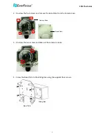
Страница 5: ...L Shaped Mounting Bracket to prevent the camera from being damaged by direct sunlight Basic Installation This installation guide provides the basic instructions on installing an EHN Plus IP camera to the wall For details please refer to the User s Manual in the software CD To mount the camera to the wall and connect the cables to the camera 1 Unscrew the four screws and remove the cover from the c...

Страница 6: ... four screws and remove the Base Plate from the Camera Case Camera Case Base Plate 3 Unscrew the two screws and take out the camera module 4 Screw the Base Plate to the Wiring Box using the supplied four screws Base Plate Wiring Box ...

Страница 7: ...cle Plate on the bottom of the Camera Case You can simply loosen the Circle Plate using a coin Circle Plate Camera Case b Loosen and remove the Cable Gland from the Camera Case Screw the Cable Gland to the hole on the bottom of the Camera Case Cable Gland Camera Case c Screw the Circle Plate to the side hole on the camera Case ...

Страница 8: ...nal wires have to be bundled into a cable with diameter ranging from 5 3mm to 6 4mm see Step d below Screw Body Screw Cap Stopper Claw Plug Stopper Adjustment Ring s Cable Gland Cable Gland Screw Cap a Remove the black Adjustment Ring if you are using a Cat 5 network cable Note that the four Adjustment Rings including one black and three transparent rings are attached on the Cable Gland If you are...

Страница 9: ...ctor then you can use the Slitted Cable Conduit Slitted Cable Conduit d Optionally insert the additional wires such as power if you want to power the camera through a 12V DC power source alarm and audio cables through the other Cable Conduit Note that one Cable Conduit can only be inserted with one cable The Cable Conduit has been tested to support cable diameter between 5 3mm and 6 4mm Please ref...

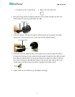
Страница 10: ...era module 8 If you have inserted additional wires connect the wires to the terminal block Please refer to 2 Terminal Block for pin assignment 9 Optionally insert an SD SDHC card to the card slot SD Card Slot 10 Stick the supplied 2 desiccant bags inside the camera case Note It is highly recommended to replace the desiccant bags every time when you open the camera 11 Place and screw the camera mod...

Страница 11: ... 7 in 4 Accessing the Camera a To adjust camera lens use the Zoom Focus screws Focus Screw Zoom Screw b To adjust the camera to a desired angle Pan Adjustment Simply turn left right for the top camera module 360 360 Tilt Adjustment Using the two tilt screws 64 Rotational Adjustment Using the rotate screw 180 13 Screw the cover back to the camera case ...

Страница 12: ...nsparent x 3 1mm thickness Black x 1 0 5mm thickness Adjustment Ring s Cable Gland Number of Cable used Cable Type Diameter Number of Adjustment Ring Used One One Cat 5 Φ 5 3mm Three Transparent Rings One Cat 6 Φ 6 4mm Three Transparent Rings One Black Ring Two One Cat 5 Φ 5 3mm One Additional Cable Three Transparent Rings One Cat 6 Φ 6 4mm One Additional Cable Three Transparent Rings One Black Ri...

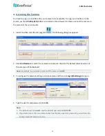
Страница 13: ... box appears 2 Click Find Devices to search the cameras connected in the LAN The default network values of the cameras will be displayed Note By default the network protocol of the camera is DHCP 3 To configure the network settings select a camera and then click Login Multi Login to log in 4 Type the user ID and password Click OK Note 1 The default user ID is user1 and the default password is 1111...

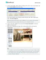
Страница 14: ...ettings please consult your network administrators for configuration details 6 To access the camera highlight the camera and click Connect to Selected IP The Internet Explorer window pops up 7 Type the user ID and password to log in The Live View window of the camera appears Note 1 You might be required to download ActiveX for viewing the camera feed If asked click Yes 2 To enable Remove Live View...

Страница 15: ...see the IP camera on a LAN WAN Internet The camera must be assigned an IP address that is compatible with its LAN By setting up port forwarding on the router you can remotely access the cameras from outside of the LAN via the Internet To remotely access the Web interface of the IP camera please refer to 7 3 2 DDNS in the User s Manual To set up port forwarding please consult the manual of the rout...

Страница 16: ...tion may require that you use DDNS for a reliable connection Please refer to 7 3 2 DDNS in the User s Manual One to One Connection Directly from PC to IP camera You can connect directly without using a switch router or modem However only the PC connected to the camera will be able to view the IP camera You will also have to manually assign a compatible IP address to both the computer and the IP ca...

Страница 17: ...ning an IP Address to log in the camera 2 Highlight the camera and then click Upgrade Firmware A browsing window appears 3 Select the firmware file evb and then click Open The IP Utility will automatically upgrade the firmware The camera will reboot once the update is complete Click Find Devices the new firmware version should be displayed in the last part of the Machine Name ...

Страница 18: ...ww everfocus co jp info everfocus co jp EverFocus Europe UK Unit 12 Spitfire Business Park Hawker Road Croydon Surrey CR0 4WD UK TEL 44 20 8649 9757 44 845 430 9999 FAX 44 20 8649 9907 www everfocusuk co uk salesuk everfocus com EverFocus India Suite 803 Housefin Bhavan C 21 Bandra Kurla Complex Bandra East Mumbai 400051 India TEL 91 22 6128 8700 FAX 91 22 6128 8705 www everfocus in sales everfocu...

Отзывы: