background image


INSTALLATION 


Warning:   

To prevent electrical shock, turn off the electrical power before making electrical connections. 


1.


Locate the desired mounting location; position housing with PIR detector and camera pointed 

generally in the desired direction and mark location.


2.


Select hole locations for direct installation or bracket mount installation. Drill pilot holes and 

insert plastic anchors into holes after drilling. If wires will be hidden drill a minimum 5/8” 

diameter hole for the power and video cables. Open the PIR detector casing by gently pulling 

the front and back covers in opposite directions. Pass the motion detector power and contact 

wires through the hole in the back of the case. 


3.


Connect the PIR detector power, N.O and N.C 

wires. Also separately connect to the camera 

coaxial power and BNC video connectors 

(observe polarity for power – connecting 

reverse polarity will damage the camera and 

void the warranty).   


Содержание ECMD200

Страница 1: ...interfere with camera operation 2 Never disassemble the camera beyond the recommendations in this manual nor introduce materials other than those recommended herein Improper disassembly or introducti...

Страница 2: ...ended 8 Mounting Use care in selecting a solid mounting surface which will support the weight of the camera plus any wind snow ice or other loading and securely attach the camera to the mounting surfa...

Страница 3: ...ide Dynamic Range DWDR 2D Noise Reduction 2DNR DC power cable and video cable and power pigtail provided Built in anti aliasing function to improve perceived video image quality PIR Motion Detector PI...

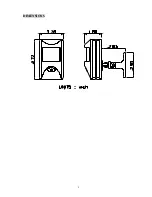
Страница 4: ...3 DIMENSIONS...

Страница 5: ...ng Temperature 10 C to 50 C 14 F to 122 F Humidity 20 80 non condensing Power Requirements camera only 12VDC regulated 100mA PIR Motion Detector PIR Detection Angle Horizontal 100 Vertical 45 PIR Dete...

Страница 6: ...s and insert plastic anchors into holes after drilling If wires will be hidden drill a minimum 5 8 diameter hole for the power and video cables Open the PIR detector casing by gently pulling the front...

Страница 7: ...r PCB NOTE If the bracket is NOT used there is no way to change the camera direction aim the camera 5 If you are using the mounting bracket recommended attach the bracket to the mounting surface with...

Страница 8: ...LED selector as indicated in A To determine the time period of N C N O relay to the alarm panel device A Max time Turn counter clockwise B Min time Turn clockwise 3 Dwell Time Adjustment MIN MAX VR2...

Страница 9: ...s movement twice within 15 seconds 6 Terminals N C N O N C Normally closed N O Normally open contacts Input power see below Relay output current 2A 24VAC 2A 24VDC 7 Power 12V DC Standby current 1mA Wo...

Страница 10: ...3 5625 8189 www everfocus co jp info everfocus co jp EverFocus Europe UK Unit 12 Spitfire Business Park Hawker Road Croydon Surrey CR0 4WD UK TEL 44 20 8649 9757 44 845 430 9999 FAX 44 20 8649 9907 ww...

Отзывы: