background image

ECE0528i/ECE0548i Mini-ITX Chassis   

STANDARD ASSEMBLY 


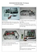
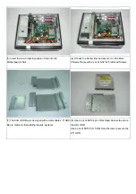
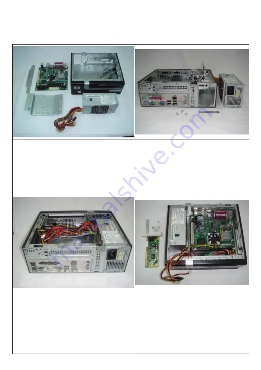
1. Before assembly, -   

Dismantle the Plastic Slim ODD Cover from the Front Panel, 

Remove the Slim ODD+2.5” Bay (Or 3.5" HDD Bay) and the 

Center Bar from the Main Chassis Frame. 


2. To install the bigger size FSP170-60SI/FSP220-6PLA 

Power Supply, -   

Break off and remove the excess 

‘Punched-but-not-perforated’ Bracket on the Rear Panel 

so that the Opening on the Rear Panel matches to the size 

of the Power Supply.   


(3) Place the Power Supply inside the case and, - 

Use 3 pcs of 6-32*L6 Hexagon Head Screw to secure the 

Power Supply from the Rear Panel.   

(4) Use 4 pcs of 6-32*L6 Hexagon Head Screws to install 

and secure the Motherboard.   

If Low Profile Expansion Card is required, -   

Unscrew and remove the Card Holder Bracket on the Rear 

Panel,  

Break off and remove the ‘Punched-but-not-perforated’ 

Low Profile Slot Cover on the Rear Panel.   


Содержание ECE0528i

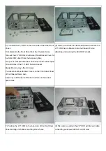
Страница 1: ...t the Card Holder Bracket Insert the Riser Card into the Motherboard s PCI Slot and Use 2 pcs of 6 32 L6 Hexagon Head Screws to secure the Riser Card on the Center Bar 3 Insert your Expansion Card hor...

Страница 2: ...eak off and remove the 3 Circular Punched but not perforated Covers on the Front Steel Panel of the Chassis Frame and Insert 2 pcs of Shockproof Rubber Cushions in the widest apart holes 6 Use 2 pcs o...

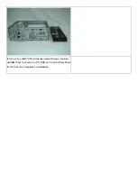
Страница 3: ...9 Use 4 pcs of M3 0 5 L8 Hexagon Head Screws included with EMI Clips to secure the 2 5 HDD on the Front Steel Panel from the front to complete the installation...

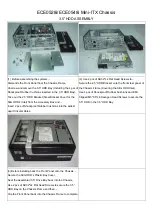
Страница 4: ...t apart Circular Holes 2 Use 2 pcs of 6 32 L4 Flat Head Screws to Secure the 2 5 HDD Bracket onto the front steel panel of the Chassis Frame Covering the Slim ODD Inlet Use 4 pcs of Shockproof Rubber...

Страница 5: ...not perforated Bracket on the Rear Panel so that the Opening on the Rear Panel matches to the size of the Power Supply 3 Place the Power Supply inside the case and Use 3 pcs of 6 32 L6 Hexagon Head S...

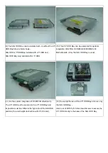
Страница 6: ...cure it on the Main Chassis Frame with 2 pcs of 6 32 L4 Flat Head Screws 7 The Slim ODD Bay is designed with a detachable 2 5 HDD Bay to match multiple Motherboards systems 8 Use 4 pcs of M2 0 4p L3 F...

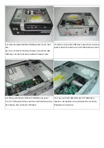
Страница 7: ...GCLF D945GCLF2 Motherboards Only the Slim ODD Bay is used 11 For the system integration of DC45FC Motherboard The 2 5 HDD must be secured in the 2 5 HDD Bay and Its position must be shifted to the rig...

Страница 8: ...only the Slim ODD Bay is used there is internal space to allow the insertion of Low Profile Expansion Card 15 When both the Slim ODD 2 5 HDD Bay are used The 2 5 HDD would interfere with the Low Profi...

Отзывы: