background image

EVE

 Audio product manual

Remote Control

13

OPERATION


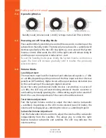
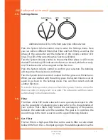
Dimly Lit Point

Only the LEDs corresponding to the selected volume level light up dimly. 

The louder the signal, the further up the dimly lit-up point moves.


!

Intermediate steps are indicated by the lighting of two adjacent LEDs. The 

level ranges from -60 dB to +10 dB, taking “0 dB” as reference point.

3.11. 

Saving Your Settings

All settings on the front and rear panels are automatically saved. The 

loudspeakers can be disconnected anytime without the settings being 

lost.

3.12. 

Remote Control

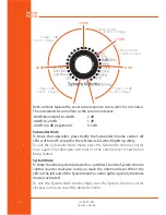
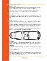
Your EVE Audio subwoofer comes with an IR remote control that allows 

you to control almost all functions available on the front panel.
In order to start using the remote control, you must first insert the supplied 

batteries in the battery compartment. Please pay attention to the polarity. 

Hold the remote control in such a way that the infrared cell points towards 

the receiver cell on the subwoofer. There should be no objects between 

both cells in order to achieve the best performance.


On Button

Use the On button to put the subwoofer in Standby mode (see Powering 

On/off: Standy Mode). Press the button again to exit the Standby mode.


LED Button

Use the LED button to select the LED mode of the subwoofer. The mode 

changes every time you press the button (bright ring, bright point, dimly 

lit ring, dimly lit point).


Phase Button

Press the Phase button to shift 180° the phase of the subwoofer signal 

(see Sub Phase). The Sub Phase LED on the subwoofer lights on. Press the 

button again to return the phase to 0°.

Содержание ThunderStorm TS110

Страница 1: ...EVE AUDIO PRODUCT MANUAL TS110 TS112 NOV 2015...

Страница 2: ...into your outlet consult an electrician for replacement of the obsolete outlet 10 PROTECT the power cord from being walked on or pinched particularly at plugs convenience receptacles and the point whe...

Страница 3: ...e environment or human health from uncontrolled waste disposal recycle it responsibly to promote the sustainable reuse of material resources To return your used device please use the return and collec...

Страница 4: ...the product and void the products warranty The use of AC Plug Adapters is cautioned because it can allow the product to be plugged into voltages in which the product was not designed to operate If the...

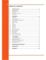
Страница 5: ...nu 11 3 6 Filter 11 3 7 Sat Filter 11 3 8 Sub Filter 12 3 9 Sub Phase 12 3 10 LED Mode 12 3 11 Saving Your Settings 13 3 12 Remote Control 13 3 13 Power Switch 14 3 14 DIP Switches 15 3 15 Mains Volta...

Страница 6: ...ning of the subwoofer and avoids the emergence of hum which is unavoidable when applying the bass reflex port design The passive radiator is on the bottom side of the subwoofer The subwoofers of the T...

Страница 7: ...XLR inputs of your studio s left and right satellites All output levels should be as low as possible 2 3 Powering On Engage the Power switch on the rear side of the subwoofer to turn it on or off The...

Страница 8: ...ections there are XLR input and output connectors on the rear side that allow the connection of balanced and unbalanced devices signal sources active monitors etc Balanced XLR pin assignment XLR 1 Shi...

Страница 9: ...u or 22 dBu depending on the position of the Max Input switch on the rear panel see DIP Switches Higher levels at the input produce distortion due to the overloading of the analog to digital converter...

Страница 10: ...he subwoofer press briefly the Subwoofer Volume control All LEDs will turn off except for the left most LED which lights up dimly To exit the Subwoofer Mute mode press the Subwoofer Volume control onc...

Страница 11: ...Volume control to adjust the filter phase or LED behavior When you are satisfied with the setting press the System Volume control again to go back to the Settings menu You can then select and edit an...

Страница 12: ...180 the phase of the subwoofer signal The Sub Phase LED lights on Use this function when the overall sound subwoofer satellites sounds a bit thin This can happen if the subwoofer s phase is offset fro...

Страница 13: ...nel In order to start using the remote control you must first insert the supplied batteries in the battery compartment Please pay attention to the polarity Hold the remote control in such a way that t...

Страница 14: ...oofer s low pass filter and to select the LFE mode see Sub Filter Mute Button Press the Mute button to mute the whole system subwoofer satellites see System Mute Press the button again to exit the Mut...

Страница 15: ...the input sensitivity of the subwoofer In a studio environment the maximum level 0dB ought to be 4dBu In such environments leave the setting at 7dBu However some studio gear allow much higher output l...

Страница 16: ...tor IEC 16 OPERATION Turn the subwoofer off Disconnect it from the power grid Detach the IEC connector from the unit Remove the fuse Change the fuse The replacement fuse should comply with the values...

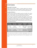
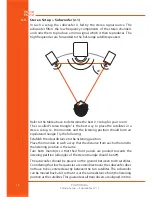
Страница 17: ...oofer and satellites should be at the same distance from the listener In a 2 1 system the subwoofer ought to be placed between both satellites see Stereo Setup Subwoofer In a 5 1 system the subwoofer...

Страница 18: ...e listening position should form an equilateral triangle Try the following Establish the ideal distance to the listening position Place the monitors in such a way that the distance from each other and...

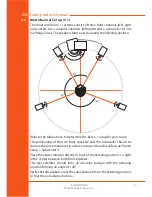
Страница 19: ...etermine the best 5 1 setup for your room The positioning of the two front speakers and the subwoofer should be done in the same manner as in a stereo setup with a subwoofer see Stereo Setup Subwoofer...

Страница 20: ...acoustics is a science in itself and it is unfortunately out of the scope of this manual However we have put together a short bibliography for you Recording Studio Design by Philip Newell ISBN 0 240...

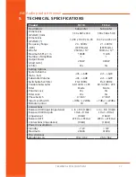
Страница 21: ...Yes Yes Setting Options System Volume Sub Sat inf 6dB inf 6dB Subwoofer Volume inf 6dB inf 6dB Switchable Sat Filter Flat 80Hz Flat 80Hz Variable Subwoofer Filter 60 140Hz LFE Mode 60 140Hz LFE Mode...

Страница 22: ...15 of the FCC Rules These limits are designed to provide reasonable protection against harmful interference in a residential installation This equipment generates uses and can radiate radio frequency...

Страница 23: ...and Stenz Managing Director EVE Audio 7 WARRANTY The manufacturer warranty is valid for a period of two 2 years after the date of purchase The warranty covers repair costs labor and spare parts produc...

Страница 24: ...Germany 4 9 3 0 6 7 0 4 4 1 8 0 4 9 3 0 6 7 0 4 4 1 8 8 info eve audio com www eve audio com facebook com EveAudio twitter com EveAudio Nov 2015 EVE Audio All rights reserved EVE Audio reserves the ri...

Отзывы: