

`
Turn ON/OFF manually or remotely via the Z-Wave controller
• Can be Included in multiple Groups and Scenes
• Compatible with all incandescent and CFL/ LED bulbs
• Blue LED indicates switch location in a dark room
• Z-Wave Certified for simple pairing and integrated home automation
• Screw Terminal Installation — requires wiring connections for Line (Hot), Load, Neutral.
WARNING — SHOCK HAZARD
Turn OFF the power to the branch circuit for the switch and lighting fixture at the service panel. All wiring
connections must be made with the power OFF to avoid personal injury and/or damage to the switch.
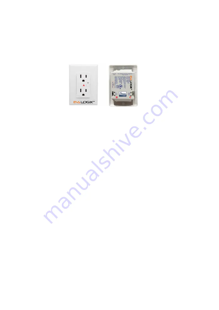
A. Receptacle
B. Lin (Black) - Line in
C. Nin (White) - Nutral in
Single receptacle wiring
1. Shut off power to the circuit at circuit breaker or fuse box.
IMPORTANT!
Verify power is OFF to outlet box before continuing.
2. Remove wall plate.
3. Remove the outlet mounting screws.
4. There are two screw terminals on the outlet; these are marked
B. Lin — Black (connected to power)
C. Nin — White(Nutral)
5. Observe Important Wiring Information
IMPORTANT!:
This outlet is rated for and intended to only be used with copper wire. Wire Gauge Requirements
Use larger wires suitable for at least 80° C for supplying Line (HOT), Load, Neutral connections.
Wire strip length:
For attachment to screw terminals: Strip insulation 1" , For attachment using the enclosure’s holes: Strip
insulation 5/8".
7. Connect the black wire that comes from the electrical service panel (Hot) to the terminal marked Lin.
8. Connect the white wire to the neutral terminal marked Nin (use jumper wire if needed).
9. Insert smart outlet into the switch box being careful not to pinch or crush wires.
10. Secure the outlet to the box using the supplied screws.
11. Mount the wall plate.
12. Reapply power to the circuit at fuse box or circuit breaker and test the system.
Basic Operation
The connected outlet can be turned ON/OFF Remotely with a Z-Wave Controller
2. Linking your Z-Wave device
Reset Outlets to factory default:
Use controller to remove device from network will reset it to factory default
Adding device into the network:
1. Follow the instructions for your Z-Wave certified controller to include a device to the Z-Wave network.
2. Once the controller is ready to include your device, triple press the front button to include it
into the network.
3. Once your controller has confirmed that the device has been included, refresh the Z-Wave network to
optimize performance.
4. The device is associated in the same group when it included in setting process.Now you can control your
Z-Wave device according to groups, scenes, schedules and automation programmed. If your controller
features remote access, you can now control all devices in Z-Wave network from mobile devices.
To exclude the device
1. Follow the instructions for your Z-Wave certified controller to exclude a device from the Z-Wave network.
2. Once the controller is ready to Exclude your device, triple press the front button to exclude it
from the network.
Note:
Your controller may need to be within 10 feet of the device to be included.
All non-battery nodes within Z-Wave network will act as repeater.
The association group supports five nodes and lifeline function.
Use this procedure only in the event that the network primary controller is missing or otherwise inoperable.
Package content
In-wall Smart Outlet-1pcs
Screw-2 pcs
Installation Operation manual-1pcs


