background image

Содержание 808

Страница 1: ... N w ffi b CONTROLLER ffiffi EIII IE ...

Страница 2: ...usl mode prc dures 9 7 4 Aubmatic mode wih mp to Point prc dures 9 7 5 Annurciation 9 7 6 Modifi lim ot mping pffie grs 9 7 7 Ramping spsed 9 7 8 Taroot sstsoint 9 Page 6 0 Alsrm 10 g l Annunc1a1i0n 10 8 2 Acknwledgement 10 9 0 Ssnsor 8ro0k l0 9 l Annunciat Dn l0 9 2 Automalictranslolto opeft hop modo I 0 10 0 Scll Tuno 1 I l0 l Pamot rs lc 14t0d l I l0 2 Pffietqrs sd Annmclati I 2 10 3 Operalion ...

Страница 3: ...ailuE wifiin ths cmltolld in srch a way as lo l66w the oulPul 6witchod on 4 Mqop essd or EolMee lajluG ln a sysf m s faitffi a vave moEmenl q valvs linkags 6 Remolo Eelpolnt lo ntroll ri3 laulty 7 o6Etim bv unouthodsed mrEonngl ed a C rbllerloltin MMulwih hlgh iPUI power Bet i I b Selpoint sol t high 8 Any hck ol maintgnan ln sowl ablo pans 4d msy ohd unloresom 6iluations ll laEvlno tho hoslot on ...

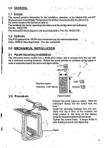
Страница 4: ...ALLATI9N 2 1 Panel mounting lnstallatlor The inslrumont sl Bve munts into a 45x92 2min culout and is seored frcm the rea with ths 2 enclossd mounting brack ls Behind ths panel provido for sutl Eienl wiring spaco in ordgrtosgparaleproporlythepower and s rgnal eblos t 1 77 18fi s tj l I _ l i Muimumpaner WTg B i8 88 rh rcknss o 2s 6mm ffiffi f e8 z i pro auie Panel Cutout Propare lh panel dlout s ab...

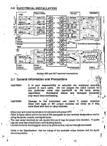
Страница 5: ...puts and signal inputs Th rear scrow lerminals do not rsquirE lhe use ot lugs tor prcper wire relEnt Pn lf sPade lugs aro used th6y should havs a self retainingf ature Unussd t rminals should 9t be usod 6 tie poinls as lhBy may b inlomally onnsc t d I 1 i lnformatlon and Precautlons iftj r Jt It ls your responslblllty to ldlate lho msxlmum posluie curont ln ach eblo Ilo nol oxcood tho ratod durr3n...

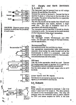
Страница 6: ...ut Connecl tolominals 19C ild 20 as shown Use appropriate mpensling eble lhermmuplE xtension wire having ths sam9 lhsrmal aml as tho them uple to which it is nnec t d vedty that orsct polarity is rgspocled at both tho thormmupl end and instrumBnt end olthe eble BTD lnput Only the 3 wire onneclion should be ussd Connecl ths msasur m9nt leads to tsrminal 19 G and 20 ThB excilalion curent is availabl...

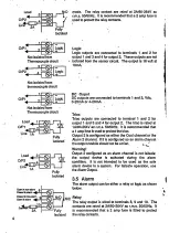
Страница 7: ... triaa Output 2 ls nligured I eith r the Cool cliannel orthe Alarm 2 channel I it is mfigursd I m alam chann l thsoulputmodulsshouldnotbealrie Warnlng Output 2 onfigurEd 6 ff dam channel is not failials the oulpul dEvicd is adivat d during ths alarm alarm dovico in a system For lailsale operat pn use lhs Aam Output 3 5 Alarm Ths ltrm oulput a be eilher a relay or logic as shown below Rslay Ths rel...

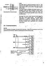
Страница 8: ...cuil should be lused and designed lo haVe lailsatdoperation EvEn in tho casg ofablownfusE Not isolaled lDm therm uplE Warnlng The alarm oulpul channel should lgyel be fined wilh a lriac oulput module For crilical alarm apptications a parallsl rsdundant syst m should always bo installedi use a separate alarm unil e 9 Eurctherm Model 106 or equfualEnt and a separals ioputssnsor RS232 Uso 3 nduclor 2...

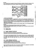
Страница 9: ...lpl b always dgsired jumpertsrminab 16 and l7t sther ll either ot th8 ommun Et pns boards is mt installsd then no nneclion n ed bo made lo lerminals 16 and 17 4 0 DISPLAYS 4 1 Upper display lunctions Me6ured value whsn lntho automaticormilual mdss Parameter mnemoniG when viewing the parai lsr list wilh lhE PAR button Ths mesursd value displayed flashes if lhs ntrollsr enloB tho dam ndilion algl i ...

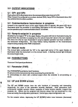
Страница 10: ...s during inspsclion ol lhs inslantanaous setpoint during ramping when PAR is dopressed 5 4 Mahual mode The manual light ndsmealh lhe M in the upp r right rner of ths upp r dbplay is illuminat d whsn tho instrument is in lhe manual mode A flashing manual l Eht indi tss the sensorbr ak mode 6 0 PUSHBUTTONS There are 4 fmnf panel pushbuttons 6 1 Parameter PAR Tho PARAMETER pushbutlon has2 funclions T...

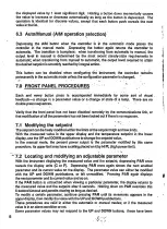
Страница 11: ...aramEtEE hs nol been lockod out if lhsre is no response 7 1 Modifying the selpoint I ThB setpoint n belroely modifiedwithin the limils ot tho setpoint h Eh and low limis Wilh the m asured valug in tho upper display and tho lomponluro sElpoint in the low r display uso lhe UP and DOWN pushbuttons tochange lhe sElpoint valug ln the manual modg th p rcent power oulput is the pametsr mniiilied by th s ...

Страница 12: ...able by tho SPr sstpoint Bmp ratg paamoler trd r mains onstill tor all ramps unlilSPr is cha ngod l 7 5 Annunciation During Emping lhe upper display shorE lhs measured valuo s in mlmal automatic q manual op ration tho low r display shils ths tatget setpolnt During ramPing sggmsnts the B lahp is ilhiminated Aftsi lh now taEst sgtPoint hai been r ached the lamP goes oul To vi w lho instantamus setpo...

Страница 13: ...lBared 9 0 SENSOR BREAK 9 1 Annunciation I 9 1 1 Overrange condition A broken thermmuple or op n ckcuit input is indi tEd by the mnemon E Sn b s6nsor break The mesured value n sos rapidly beforo the sEn r break indi tion murs The open circuit input is detscled by an overrange input signal excseding ths milimum of ths linearizalion tablE Tho ntrcller th n onleE the opsn l p mode and oulputs lhs sen...

Страница 14: ...nt A sell tune prcedurB from setpoint is psrlormed s lpoint This cm applyto either an endothErm Eor must b moled lo mainlain ntrol point il tho measur d value is nsar lhg ntDl an gxothermicpreEssoraprocesswhich 10 1 Parameters calculated Both typ s of self tuning calculats valuBs for the PID parameters ProP prcportional band lnt t intsgraltime nslant der t derivalivo timE 6nslant ln addilion the t...

Страница 15: ...l be placed intoldl Eor Hold bslore intiating sell luning o PID ntrolwith ramoed setmint modificat pn Self tuning ovsrddes ramping if the unil CAUTIONI l lho unlt ls conflgured ln lhls way tor tho r6a n ol preventlng shock to tho load sell lunlng should not bB used asth 808 847 sell tunlng algorilhm puryosely shocks ths syslam 10 2 Parameters and Annunciatlon Two ditlerent param6tErs can bB used t...

Страница 16: ...lon r Possiblo senarios ol s ll tuning op rations are pr s nted her llashes inlhe lowerdisplay Do not make any adjustmsntsto the this period Ths self tuning isjinished whent u are alarm annuncialions Hl AL Lo ALord tunEl Th6 value of r lalivg 60l op ration ls assumsd to gain rEL be rrEcl c nEno AL tn t rhe 2O9 non evaporative ling tltl 10 3 1 Start up tune r 1 rr tr r 1 q i i Figure 1 illuslratss ...

Страница 17: ...Figu 1 Stad up tune heat up Pmt Figurc 2 stdl up ture c l d n e CP r 14 Figurc 3 Tmo al filptint endohmic p ess ...

Страница 18: ...E Exlernal inlluence Figure 5 thes ll luns rculine aborts Ths algorithm waits lor a time b rors aborting this time is variable ad depsnds on many faclors oata gathsred from ths p e r aclion curvo aro used aslhE ur lordetermining the PID parameters in lieuordalarrcmtho ffiillations Thislomot aborl uld osurin amulti zoneappl Eationwhot an adiacent zon is adding hoat which Bl8vates ths t mporature of...

Страница 19: ... s Fohl CP Figun 4 Tuno at serpint exohmic pto ss Figun 5 Statt up tuno atf n h t only I l I a 16 Fig rc 6 S n up Tqe abort heatl o ...

Страница 20: ...t rg lulion doos not sutfer Tho nominal ranggs oltho input adapters alrEady have a 20 overdrivE latq d slgn d Into thsm on lho positivg side only so that an IAIOV en bo sal ly us6d for a signal wilh a l0V mdimum NOTET Ttolnpuladapterlncroas sthapanoldopthotthecontroltartoZ l05lnchsg 180 5mm Wrlng Refer to 3 3 for ths onneclion and wiring of thg input signal lto I t 9 E 100 hElfl lnF r 6lgd hV ua t...

Страница 21: ...display units tl the input signal causes thE disday value to rall bslow lhis thr shold the ntroller snlors thg sensor break ndition ss S4 4 3 Lo L b normally sel lo 5 otlhe minimum us rulssneroutpul si nallevelto allowloroperation downlo mlnimum withoul ntedng ths sensil br6ak ndition CAUTION Hl Land Lo Lsre not alarmsand do not ptovldaoleclrlcal slgnaloutpub Ussthcalarmoulpulora parsterodundantal...

Страница 22: ...d mplotion Applyasignaltolheontmllerequdrisome known highvalus This isthe s nd Setup point P2 Th lnputs rgnal valuE usod doos nol havelo be xadv atlh6 span point but should be as nsarspan as possible Repeattho above prccgdure substituting P2 and the display valudonssponding to tho s nd input signal Eslablish all remaining paramelers rorthe ontrollo based on the rsquksmenls ol the applrcarcn i 11 4...

Страница 23: ...ho lo 6 dkpby unti it 6ospon lo tlrc hruc Epcmled i1 w roa1 S i9P lY ql r ri l ft q a 4 IU1 irj iii i 1 l r r si i i r 6rjiriri Jnt Iq i s trl r ii E rirlr ril ii bs ia n 0r 6 D p 6 PAB 9 I rc i 7 Dop UP lo allim l j iJj j rIfr r i 11ta Iji r i J r1i t n6 rr j i i 0 _ Ji ll J sr i 8 Dffi PIF r r r 8 9 Attr 5 s nds tho s llE ol lho li6l slup p inl b 6m9l tod Repod peoduo lo tho 6 nd slup poinl P2 i...

Страница 24: ...mm6r ntrcllor g nerates a ixod lomat 4 segmonl program rmp dwell ramp dwell The 4segmsnts ar8 exrcuted in sueession when tno firit isiinisnea liE s nd is automalically startsd and so on untilthE fourth segmBnt is 6xsutod Tho program can bs xsuted betweon 1 and 200 times or continuousV Examples ot vaious p rcgims following thls lormal aro glven in Figure 10 12 1 3 Ramp segments Ths selpointlorthB t...

Страница 25: ...nother Figuro I 1 shows examplos of thBso slalBs The prcgrammsr state selsdion is available undor the Prog parffiEtEI in the scroll list Idl When ths prcgrmmer is placed into ld LE it b havss as a standard ntlollerwith the ntrol selpoint d tetminBd by tho vatug shown on lhs botom disPlay the base setPoinl Allet mplolion of a program Le lho snd of the lounh segmsnt the poglammet aulomatically placg...

Страница 26: ...amp Dudng a dwe ssgmEnt holdbacl guarantess a minimum soaklime by stopping the clock il the measured valuE deviates outs xjg of th6 holdbek band Tho progEm retuns to ru n on tho doviation has reducgd 6 long as Hold is not sslectsd The mnBmonic Hb is slrictly an indication and is not a sBleclion under thB ptog paEmeler Available only wilh software revision o2 Oo or greatsl 12 3 Program control meth...

Страница 27: ...srrdd P tun tun Tlm tun tun BeRbMM run tun Tlm C MA tu dW M poM eF tua M b M dM Figu 12 Hol ack ennples Hb Tlm a 24 ...

Страница 28: ...gnm thstsrminals muslbo opensd and shon d lo launchlhs program again thE r6ar terminals are open circuit unlil run is att mptsd at which tims lnto Hold tl lhs plogram is drr nlly running op ning tho r il t rminals pla s the programm r into Hold Hold tun Hold un ldrE td tE tun C gee MMtu M tu drv lbi d Ntu NMt I Figu 19 Use ol Bat tanioal nnacties 16 and 17lq Nogamet c ttol AAWO rq Whsn Ct rl is se...

Страница 29: ...ollhis paramstgr indicates thg time r maining in ths dwBll segm nt rlh valuo is viewed whilo thg progrm is cutrentlyinthispart EulardwEllsggmEnt ThEsggm6ntisskippsdildl Es ltoz ominutes l r 2 ramo2 Tho Ele at which lhe setpoint rffipsrrom Ll to L2 aft romplet nn o L1 Adiustable lrom 0 01 lo 99 99 display unils p r minute L2 lerseugyelS Ths targst valuo to which the selpoint ramps aftorompl tion ol...

Страница 30: ...tato lamp R Tho LED immediatsly below tho R legond on thg lascia indiGt s lhe stats ol lhe pDgram OFF ldlE ON run FLASHING Hold or Hb NOTE Tho R hmp als lndlcates rsmp lo slpolnt ln progress llr sP aM not Pro0 ha3 baen selectod under Ctrl 12 5 1 Programmer state display Ths paramster Ptog rell c1s th current stats of lhe progGm Program ssgment ll tho program is in EilhBr ru n H b or Ho ld prossing...

Страница 31: ...unappsariinthelowor display Either pr s PAR u lat the display lims outlo enter the ru n progrm statg o Frcm lhE rear lerminals tl lErminals 16 and 17 ilE open circuit shon lhem togethor tl thg tBminals aro shorted logsther opon circuit them and then short them togEth L o Throuoh the oxlernal mmunicafions mrt Thls requtes modilication olths oplional stalus parameter os using the oxternal mmunicalio...

Страница 32: ...F ErammEr b in Hold the prcgramm rclock is stopp d Tho tlme lapsed that the pogEmmer is in Hold tfeciively lEnglhEns lho total run time ot the p6gram o Changes madetoparam ters LC r 1 Ll dl 12 L2 dnd d2duilng Hold arsvalid NOTE h ls posslbl lor lho programmer lo be ln Hold lnd Hb slmuttaneously Io rasume lh avolullon otlho proglam un must bc aolectod and tho holdback6ndltlon musl ba clssted NOTE H...

Страница 33: ...es modi icalion of tho oplional slatus param ls os using the oxtornal 6mmunietions ppi6l o ln bothcasesthe state lamp R exlinguishEs to indi tethatthe prcgEmmer is lnldl E IDLE characlorlsllca Modifications made lo arlparametErs in ldlE are permanont 12 6 4 Ending a program Four options aro available to tho user al the ond ot a program as shown in Frgure 15 Ed Figup 15 Metpds ol endog ptugms 12 7 ...

Страница 34: ...mado lo thesg palamotors while in ld lE arc pomanenl Any changes made tolhEss parameters while in Ho ld causB a t8fipola ychange valid onv duing the padiculal it ration ot the program loop o Ths programmBrdoas not p rmit anychangss to be mads lo th6so parametersduring run Ths base sgtpoint SP along with holdback band Hb and the othBr non program paramsterc cn still be lreely and pstmanBnlV modilie...

Страница 35: ...lo low6larms ItlhE alarms are non latching clGsing the alarm solpoint lnto lhe safg reg pn snds the alarm ondilion Dovlallon alatm Ths doviation alarm bandlolloffithecuilentlyactivo setpoint tlthe measured value canot lrack the 3 lpoint within tho bounds ol lho dgvialion alam an alarm ndition ls gsnotalsd A Bdtsnb d lal kt h lts L h alam 8 Eohsvbt ol N tatdl dadale alm Figurc 17 Ranp lo sepoint op...

Страница 36: ... I 808 driving a heauc l load and fitted with an audibls alarm 808 11 T1 R1 NO NO4AJHC21 5 BT 6sd3 gM L M f o o E m 33 ...

Страница 37: ...Eu fl Eu6tr m BFtusI T l rto ll 66lml rorll 6619 3 t l r i l l I l to otum Contd Udbd Coh bd Wd6eb Ll 56 25 5721ll T 1 r52t852 tor m5 rmg Srol til it1 t Overeeos Componles f Authllo Hq trq luEhc6 trr Ud E rcfr m Umld Td pir Srdnry l2l 777022 Ll phd Hqs r it l5l 8733826 LluM7a362 T ts6t257Errf U Eurcfr mAutoholl6 5A Td phm tp t78 6dl9a3 Tda 38m38 EUrEil f E tu178 3524rc Ap iml frd T t t pt ml rOl r...

Страница 38: ... power in auto read only Slalus word hexad cimal Optionalslatus word Exlended slalus word 53 50 4F 50 53 57 4F s3 s8 53 sP OP SW OS xs Errorvalue Local setpoint 1 High alarm selpoint Low alarm setpoint Deviation alarm selooint 45 52 s3 4C 48 4 1 4C 41 44 41 ER SL HA LA DA TI TD HB IB XP Proportional band lntegral time Derivativs lime High cutback Lowcdbad 58 50 54 49 54 44 48 42 4C 42 CH cc BG BP ...

Страница 39: ...nd fused appibpriately A snubber may be required Snubbers 1 Connect snubbers CZ 4O398 22nf l00Q across the appropriate output or alarm relay contacts when driving AC inductive loads mechanical contactors and solenciids Do not use snubbers when driving high impedance loads The snubber passes lmA in l20Vac circuits and i 2mA in 240Vac circuits this is sufficient to hold in certain relays with high i...

Страница 40: ...ld always be backed by a suitable mechanical disconnect switch Hazardous almospheres This unii is not suitable for use in areas subject to hutrdous atmospheres No Eurotherm Controls product should be connected to a circuit which passes into or through a hazardous area unless appropriale precautions are taken even though the instrument itself may be located in a safe area Such an installation shoul...

Страница 41: ...puts Voltage divider network is required resistors supplied by user Refer to table for suggested values Resistor specifications 17o 0 125W minimum tl00ppm metal or metal oxide film Coullon Use of the shunt or voltage divider inhibits operation of the sensor break detection feature Scollng procedure There are two methods of entering and scaling linear inputs Linear a 2 point scaling configuration c...

Страница 42: ...300 0 or 0 01 to 30 00 orocess units min Alorm function selected in configurotion AL I setting irrelevonl for sensor breok olorms configurolion codes To lesl olorm operolion Hold UP or DOWN buflon unlil lESl oppeors releose then press lhe butlon ogoin Alorm slole should toqqle HYl Alorm I hysteresis l C or 1 F lo upper ronge limil Lineor inpuls I io 9999 0 1 to 999 9 0 01 to99 99 d r Deviolion olo...

Страница 43: ...a ro st sf Model i I I I I t I I I I J 4S ...

Страница 44: ...deto ensurethe accuracy otthe lnfomatlon ln lhls manual However ln order to malntaln our technlcal lead we are contlnuously lmprovlng our products whlch could wlthout notlce result ln amendments errors and omlsslons We cannot actept responslblllty lor damage lnlury loss or expenses lesultlng thereln 1992 Copyrlght EUROTHERM AUTOMATION S A FRANCE l 4255 Solld state comador User s Manual Part No HA ...

Страница 45: ...EUROCUBE Series 4255 Solid state contactor page 1 General description 3 CONTENTS 2 Coding 3 lnstallation 5 9 25 29 4 Control signal 5 Fuses 6 Technical specification H E E E E H H EUROTHERM 33 1 ...

Страница 46: ...I I i iI i I 1 t i 1 l 1 t t i t I I t EUROTHERM 2 ...

Страница 47: ...etween the load supply voltage and that to the controller The type of input signal is loglc operating in On Oft mode When ordering the user has the choice of DC or AC options Two voltage leveloptions and one cunent level option are available for the DC input signal Three voltage level options including the voltage range 100 to 240V are available lorthe AC input signal The switching ol 4255 solid s...

Страница 48: ...l in the case of overheating e 9 lan lailure Fuses and luse holders are standard they are extemalto the unil but are specified lor mounting on the same DIN rall The fuse and luseholder assembly must be specilied by the installer and procured at the same time as the 4253 by means of a separate order There is an optiona load monitoring facility partlal load lallure detectlon PLF which enables the de...

Страница 49: ...Codlng 2 CODTNG 2 1 4255 Solid state contactor 2 2 Fuse and fuseholder assembly 2 3 Descriptive label page 6 7 8 H EUROTHERM 5 ...

Страница 50: ...put DC signal Options partial Joad lailure output contact open in alarm i t I I i 4255 E H Vohaoe ranoa Code 120V 240V 415V t40v 4AOv 120 vohs 240 vohs 415 vohs 440 vohs 480 vohs Fan suoolv Coda 100v 110V120 200v 220V24 J 000 Wilhoul lan Fan vohage up to 75A 100 and 125A 1 00 vohs l 1 0 to 120 volts 200 volts 220 to 240 volts lnoul llooic conlroll Code DG signal AC sional LGC ACL Oplion Code Parti...

Страница 51: ...mbly for a 4255 solid state contactorwith maximum curent of 15A FU1038 16A 00 Fuseholder Current End Code for nominal contactor Code Code current 154 254 404 60A 754 100A 125A FU1038 FUl038 FU1451 FU22s8 FU2258 FU2760 FU2760 16A 25A 40A 60A 754 1004 1254 trt L a o o I EUROTHERM 7 ...

Страница 52: ...l a descrlptlve label Model 4255 Nominalcurrent 40A Maximum vohage 240V Wlthout fan cooling DC input signal PLF option relay contact open in alarm mode 42sSI 40 N IOVIOO0 LG C P LF 00 EI EUROTHERI I TI RIHIIIE EN6 AND ll0DEL r 255 404 t0V 000 LGC PLF 00 N 000001 001 t00L 07 t92 ANY IHER FUSE IIII ALIDATES EU0RAilTEE FERRAZ 194779 0903 68500 2 10 INPUI LOEIC DC AUIILIARY SUPPLY l l 8 EUROTHERM ...

Страница 53: ...details 3 2 Mounting 3 2 1 15 to 60A models 3 2 275 to 125A models 3 3 Wiring 3 3 1 Termlnal ldentlllcatlon 3 3 2 Slngle phase load 3 3 3 Three phase load 3 4 Setting up partial load failure detection page 10 12 14 15 16 16 20 23 24 c 9 s l o E EUROTHERM 9 ...

Страница 54: ...ent between 15 and 60A and in fig 3 2 for models with a nominalcurrent between 75 and 125A W D Flg 3 1 4255 Dlmenslons nomlnal current l5 to 60A ooo rI lr tqt II o o o o Cl G o tr Dlmenslons mm Nomlnal current 15A 25A 40A 60A Height width Depth H w D 134 134 134 116 155 134 116 155 98 98 94 130 Weight kg 1 1 1 2 0 6 0 8 10 EUROTHERM ...

Страница 55: ...r I lt I i I I I t F I i I I I t I I I w D Flg 3 2 4255 Dlmenslons nomlnalcurrent 75 to 125A c 9 s cl o L Dlmenslons mm Nomlnal culrent 75A 1004 125A Heighl widrh Depth H w D 190 117 190 190 117 190 190 117 190 Weight kg 1 85 2 0 2 0 EUROTHERM 11 ...

Страница 56: ...ed DIN rails using mounting plate and clips Stack outllne t 97 75 1 t I mm 6 5 a T I I 1 62 I r lz ____L___J_ ___ krl for nominal currents 15 and 25 A lor nominal currents from tlO to 125 A Flgure 3 3 Mountlng plate To mount severalunits on the same veilical a minimum gap ol lOcms is recommended between units ttu 1tl3 12 EUROTHERM ...

Страница 57: ...g 3 4 I t 1 12 mmt0 5 85 mmt10 I 6 f q gomm l l so mm l I I t I I l Nominalcurrent 15 to 60A Nominalcurrent 75 to 125A Flgure 3 4 Drllllng template for bulkhead flxlng Cllps are used lor DIN rail mounting The rails may be symmetric or asymmetdc 101 Flgure 3 5 DIN rall llxlng holes The rail is supplied pre drilled with fixing holes of 6 5mm diameter in a length suitable foi mounting in a 19 rack 48...

Страница 58: ...tricalor asymmetrical DIN rail bt ral adaptor Each unit is delivered with screws and a set of two lixing clips as standard rel EUROTHEBM BD173730 425S DIN rail Mounting plate Fixing clips M6 screws Flgure 3 6 4255 Flxlng nomtnat current 15 to 604 Cllp on flxlng i l i I l I 1 I I I I I t I I s loI o o o o tr 9 g G ID E o o u D I 14 EUROTHERM ...

Страница 59: ...DIN ralls by means of a base plate and three fixing clips ref EUROTHERM 8D173730 425S 12 mmt 1 5 Jt tl 85 mm t10 I I I I I I N E tPs DIN rail Clipon lixing cl Mounting plate M6 screw qh Flgure 3 7 4255 Flxlng nomlnal current 75 to 125A a o o s E o c oo EUROTHERM 15 ...

Страница 60: ... signal DC or AC and according to the value of nominal stack current L1 Earth Load used Common l l i lft5 Tilllrn l I aecordlng lo system lilit r Used wlth PLF or IPF opdons Flgure 3 8 ldentlflcatlon of 4255 termlnals 15 to 60A nomlna current Control signal DC Pluggable connector EUROTHERM D6latn Fail S UiI Adlust f r ao l6 to L b b LOAD CHARGE LINE LIGNE Prcsence ol control slgnal 16 EUROTHERM ...

Страница 61: ... Presence o control signal L1 Not used Earth Load Alarm relay contact Pluggable connector Common PLF supply Neutral or Phase L2 according to system t Used witi PLF and IPF options Flgure 3 9 ldentlflcatlon ot 4255 termlnals 15 to 60A nomlnal current Control signal AC tr 9 g E o s EUROTHERM 17 ...

Страница 62: ...al Prcssnca of control l lot used Common PLF supply N6ulral or Phasc L2 acoodlng to sysle n Alarm relay conlac Fan supply ror 100 or 125 A curents Usod wlth PLF or IPF optlone Flgure 3 l0ldentlllcatlon of 4253 termlnals 75 to 125A nomlnal current Controlsignal DC Pluggable connector 18 EUROTHERM ...

Страница 63: ...E Proscnco oil control c 9 g G o c Not uscd PLF supply Ncubal or Phasc L2 rccordlng to systcm Alarm rolay clntscl Fan supply fot 100 and 125 A currcnts Common J Uscd wlth PLF and IPF opdons Flgure 3 11ldentlllcatlon ot 4255 termlnats 75 to 125A nomlnal current Control signal AC Pluggable connector EUROTHERM 19 ...

Страница 64: ...omecanlcal trlac or optotrlac Flgure 3 12 Example ol4255 wlrlng 15 to 60A nominalcurrent lnput signal AC lfi 2tl lVac 22O124OV system Only lor PLF or IPF optlon r The impedance of the control contact protection circuit must be 20kohms tor 24Y input 36kohms for 48V input or 600kohms for 1fi1 240V input i 9 g o o L Ertomal fusc lor thyrlstor prot6ctlon o o LOAD s 425S P LF INPUT O EiITREE Fusc 0 s A...

Страница 65: ...oooooooo Exlrmal luro rorthydltor protrctlon Singla phesc load t t Belay contacl wilh option Opcn in alarm stalc PLF Clossd in alarm stalc lPF Flgure 3 13 Example ol4255 wtrtng 15 to 60A nominalcurrent gB0 415V system Controlled by EUROTHERM 902 controller lOVdc input Cutout devlce lsolalor lnterruptor breaker contaclol etc t Only lor PLF or IPF opilon EUROTHERM 21 ...

Страница 66: ...M 902 controlter 1Ovdc input Force ventilated lan suppty 220V without lan cooling for 75A nominal curent Hl o L o U a o L Ertemrl fur lor lhydstol prolecllon Slngle phase oad Fu3e 0 5A EUROTHERiI UilE r oeo cltAmE o LlonE H L N P L F o h PUT ENTREE TEMPERATURE CONTROLTER 9 n a Loglc output x2 A3 22 Only for PLF or IPF optlon EUROTHERM ...

Страница 67: ...xample ol wlrlng oltwo 42SS sottd state contactors conroillng a lhree phase load 24Vdc input Onty lor PLF or IPF optton Control signal Three phase load YorA o tlltE o t LI IE 42sS 425S P LF INPUT O ENTREE P LF INPUT O ENIREE f f oo o oo o o Fuar 0 5 A Extomal uso Frr 0 5 A E h E E EUROTHERM 23 ...

Страница 68: ... IPF optlon The contact is open in the normal state i e not in alarm Relay contact ratlng 0 25A 250Vac or 30Vdc lsolation 250vac Settlng ln orderto carry out PLF adjustment the cunent must be greater than 15 but not less than 2A of the nominal unit current As a general rule since the load current is less than the nominalthyristor current the following setting must be carried out Check that the thy...

Страница 69: ...I Slgnal 4 CONTROL SIGNAL 4 1 DC signal 4 2 AC signal 27 28 H EUROTHERM 25 ...

Страница 70: ...e Bootean On Ofl There are two options which may be chosen when ordering a solid stale contactor DC signal AC signal A lront panel LED i ndicates the presence of the control signal I I 1 J I 1 i 1 j i I 1 l i l i I I I I t i a i or tI I i I 26 EUROTHERM ...

Страница 71: ... on the terminalblock 20 mA culrent On l 5to50mA Ofl l 0 5mA Vottage drop burden at 20mA 6V 10 V voltage On U 8to20V Off U 2V 24 V voltage On U 16to32V Off U 2V lmpedance lnput Reslstance Nota 20mA 0 Each input is in sedes with 2 diodes Voltage drop about 3 5 volts 10v 390 24V 1590 6 L 9 U I EUROTHERM 27 ...

Страница 72: ...ntrolterminal block at the front of the unit 24 V voltage On U 20to30V Off U 6V tl8 V voltage On U 30to55V Otl U 12V l0 to 24OV voltage On U 90 to264V Otl U 50V lmpedance i i i I I I I 1 lnput lmpedance at g 0 Hz about Nota 24V zl dt Each input is in sedes with 4 diodes Vottage drop about 6 Volts EV 3K 100 to 240V 9 sko 28 EUROTHERM ...

Страница 73: ...I Fuses 5 FUSES H EUROTHERM 29 ...

Страница 74: ...correc t fuse ls used recommended luses are glven ln the lollowlng table The fuseholder is intended for mounting on a symmetrlcal DIN rail For asymmetrlcal DIN rails an adaptor must be specified lor the fuseholder ref FE 018700 supplied as standard when the fuseholder is ordered 1 t I A fast actlng semlconductor protectlon luse ls lntented for use ln the 4255 solld state contac or Thls luse cannot...

Страница 75: ...e fuse holder sub assembly code 15A 25A 40A 60A 754 100 A 125 A 20A 324 50A 804 100 A 125 A 160 A cH 260024 cH 260034 cH 330054 cs 173087U080 cs 173087U100 cs 173246U125 cs 173246U160 cP 018525 cP 018525 CP 171 180 cP 173083 cP 173083 cP 173245 cP 173245 FU1038 16A 00 FUl038 t25At00 FU1 t51 I 40A100 FU2258 60A 00 FU2258t75At00 FU2760 100A 00 FU276o t i ts At Oo Fuses tr o o o ...

Страница 76: ...1 Fuse holderdlmenslons D m o o o o TL Dlmenslons mm Fuseholder FU1038 FU1 t51 FU225a FU2760 Helght wdrh Depth H v I D a b c d 81 17 5 68 715 38 36 5 95 26 86 2 7 5 t t 40 5 124 35 90 4 il 42 2N 54 107 71 75 il I I I 32 EUROTHERM ...

Страница 77: ...ix parallel heater elemenls LED indication and openinS PLR or closing tPF of alarm relay contact Contact rating 0 25A 250Vac or 30Vdc Control signal isolated from power lo lP20 lEC 529 Distances comply with lEC664 RC circuit snubber and VDR External luse to be ordered separately Control detachable Wires 0 5 to 2 5 sq mm Power and earth screw terminals 15Ato 40A 1 5to 10 sq mm cables 60A 2 5 to 16 ...

Страница 78: ... 33 36il 832 0 Kom Errolh m Kort Lld Suite t903 DaeiooBuilding 132 19 ChungdaftDong KangnarrFKu Sooul 13 100 Tslgphono 821 2 543 8507 Fa 82 2 545 9758 llalhqL d Euotham B V Johan F Eostraal 1 2382 HJ Zoslerlvoudo Tolephone 3ll 71 4l I 841 TEIEX 39073 EIBNL NL Fax 31 71 414 526 lloruey El othcnnA S Pct Boks 199 N 1412 Oslo Telgphofle 44 66 80 3 l 30 Fax 44 66 80 33 31 I spoln Euothcm Etp llSA Callo...

Страница 79: ...ON OFF CONTROLLER PROCESS ALARM TYPE 106 INSTALLATION AND OPERATING NSTRUCTIONS Part No H4016860 106W 5 ...

Страница 80: ... low alarm 028 036 Scale Process 106 See inputs and scale ranges See in and scale 1 15 230 t 15 50 60H2 1 0O l2N l 1 5 o 50 60H2 19 25 Screw Termanals Dorvnscale t c break std with 036 output Upscale t c break std with 028 output Scale stops Latching alarm and reset push button Controller version LED illuminating when relay energised o9 24 50 49 59 85 II l t Basic Product Scale Supply ...

Страница 81: ...The normal function of a Eurotherm model 106 is to act as r I Position of Reset swilch button z V U ...

Страница 82: ... o20 DegrecScales a Q a EEEEEEsEEH o23 o22 lron Constantan J lronconstantan DIN 4371 0 NiCr NiAl K Copper Constanlan T PttS Rh Pt R PNO Rh PI S Copper Constanlan T Nicrosil Nisil Pt Resistanco thermomeler 100 ohm at 0 deg C DC millivolts no GJC Linear o24 o25 026 090 026 026 o28 o2a 121 70 97 98 01 017 02 248 07s ...

Страница 83: ... Copper Constantan Pt13 Rh Pt Pt10 Rh Pt Copper Constantan Nicrosil Nisil Pt Resistance 100 ohm at 0C DC millivolts no CJC Linear F Dcgrec Scales tlllt H R EE 6666 uE EEREqSEEE 8 e 3 285 492 732 244 48 138 25 lr o o 6 11 o E o o o1 02 03 04 05 06 1S 45 70 97 98 t19 119 124 126 136 136 298 138 110 ...

Страница 84: ... blade ideally between 4mm and 6mm wide under one or both ot he front prongs inside he sleeve Push tilards the rear until it is possible to litt he clamp inwards Gently release the pressure on the spring Fully insert the sleeve into the cut out with the open section to the right Replace the lwo damps by locating the rear of each in he slot as shown in the diagram As before with a screwdriver blade...

Страница 85: ... in anlined spaes Connections and Wiring Electrical connections are made via 2 5mm screw clamps or 1 4 double faston terminals recessed in the rear of the sleeve For instruments fitted with screrv clamps belore inserting he wires in the tsrminal blocl ensure he screws are undone sufficienily to allol the wire to be positioned correctly A 0 5sq mm or equivalent wire size is adequate for low current...

Страница 86: ...rmocouple break prctection is standard as upscale for a 28 ouPut and downscale for a 036 output Reslstance Thermometer 100 Ohm Platinum resislance hermometer BT connections are made to terminals 1 1 12 and l 3 as shown Generally a 3 wire heavy duty RT has he terminal block on irs head numbered as in he diagram whilst a standard type has two blue leads equivalent to 1 and 3 and one red lead lt a 2q...

Страница 87: ...stor The alarm state LEO is otf when he relay is energised unless option 85 is called for Type 028 output The relay gives protection against over temp raturo conditions in which the relay d energises in alarm aborre setpoint and an open circuit lhermocouple or RT gives upscale break prot ction This is he type normally used when the inswment is to lunction as a controller Type 036 output The relay ...

Страница 88: ... shown in the diagram below and lever fie plastic moulding away from lhe scale drum Holding the stop thus tum the setpoint to he required maximum temperatJre and release he sbp ensuring it is lully engaged in the drum A similar procedure is followed if a minimum temperature limit is required rotate the drum to zero disengage he stop in he upper cut out turn the setpoint to he reguired minimum temp...

Страница 89: ...e upon connecling the supply the lowest errorindicating LED will light showing that the temperature is more than 3 of span dornscale a small arrow masking the LED indicates this The relay will be either energised output 028 or de energised output 036 the alarm state LED will be off or on respectively As the temp rature approaches the alarm point the next error indication LED will light showing hat...

Страница 90: ...check monitor voltage on alternative supply terminal Absence of voltage indictes transformer failure d Failure of IC2 Action a Repair supply mnnections b Replbce LED board see maintenance manual or contact Eurotherm c Check cause of failure if possible replace transformer see maintenance manual or contact Eurotherm d Beplace lC2 Note ll a lault is sus ted in he thermoauple ot thenro upte interanne...

Страница 91: ... Wiring Schematic 1Oo Alarm Unit 28 or 036 ouPutt 106 Lil fPIl t t f Tl 2 N rS l I l 3 1E 1 tztw sa r W 1t l7l1a w 1 e 1to 7I rr1 rrt 6 3 E E E E E E fl E E tl E E E H d Cqbr B Am Srtbnt br lEta6 a Arnuc l I ...

Страница 92: ...106 wired as Controller N L zov Lod or CcLd Fu F6e lal 6 tto tt fdt tw l6tsY LlOl rsl l 106 Cori ff BL lltA Rae 8T S ffi Ldd ...

Страница 93: ...damage either to the plant itself or its contents then an independent protection device must be provided The best form of protection is a completely independent policeman This is a separate over emperature alarm with its own thermocouple or sensor and on alarm will pull out the main contactor or shut off the valve to ensure the plant s safety e g i Thyristor i unit i il litted Controll r a lsolato...

Страница 94: ... Miller House Corporation Street Rugby WaMickshir CV21 2DW Telephono 0788 56201 l Telex 3 1 l 874 Fa 07 88 53 62 49 Noilhem Arca Norlhem Countieq Nolth Wales nd Scotlsnd Eurolherm Ltd 4 5 Chelham Coun Calvar Road Warrington Ch shirs WA2 8RF Telephon 09251 5721 1 1 Telex 629852 Fil 09 25 41 30 99 Sales and Service in over 30 countrier For counlries not lisled abovs all enquirievordsrs to Eurolherm ...

Страница 95: ...E UROTH E RAA r l ttr l ti r per ti n e r r l ig r rr ii tll lZi ...

Страница 96: ...NECTED POWER SUPPLY IS OF A VOLTAGE COM PATIBLE WITH THE APPARATUS AND IS FUSED MAKE SURE THAT ONLY FUSES WTH THE REOUIRED RATED CURRENT AND OFTHE SPECIFIED TYPEARE USED FOR REPI ACEMENT THE USE OF MAKESHIFT FUSES AND SHORT CIRCUITING OF FUSE HOLDERS IS PROHIBITED WHEN THE APPARATUS IS CONNECTED TO ITS SUPPLY TERMINALS MAY BE LIVE AND THE OPENING OF COVERS OR INTERNAL ASSEMBLIES IS LIKELY TO EXPOS...

Страница 97: ...s External Power Supply 4 5 RTD lnputs 4 6 Strain Gauge lnputs 5 0 Configuration 5 1 Display and Keypad 5 2 Entry of Numbers 5 3 The Main Conliguration Menu 5 4 The lnput Configuration Menu 5 5 The lnstrument Configuration Menu 5 6 The Alarm Configuration Menu 5 7 The Retransmission Configuration Menu 6 0 Operation 6 1 Electrical lnput Value 6 2 The Operator Menu 6 3 Remote Conlact lnputs 7 0 Main...

Страница 98: ... the lront panel presents to the operator a maximum of 6 LED characters 5 active digits Two separate LED indica tors signal the status of the two alarms The instrument is 1 8 DIN size and designed for either panel or bench top mounting Hardware for panel mounting is furnished as standard Separately specified options include alarm relays isolated signal retrans mission transmitter power supply seri...

Страница 99: ...nvironmental Relerence Temperature Operating Temperature Storage Temperature Relative Humidity Rating Power Transmitter Supply Strain Gauge Supply Supply Voltage 0 01 of basic range in use 0 1 F or C 0 1 of basic range in use 0 2 c 0 5 pVfC from 25 C 1 5 C from 25 C 50 ppm C 25 c 2to55 C 40 to 80 C 5 to 90 non condensing NEMAl GeneralPurpose 24 Vdc at 35 mA max 5 Vdc into 300 Q minimum 85 to 264 V...

Страница 100: ...ss in D 7 segment 56 in LED Green or Red 5 value plus 1 units character 3 sec Relays Two SPDT 2 A 24O Vac 500 VA or 30 Vdc 60 W Physical Terminals Case Material Case Size Bezel Size Display Type Color Digits Update 92 0 08 0o mm 3 63 03 oo in PANEL CUTOUT 45 0 r 06 OO mm 1 77 02 00 in 125 mm 14 mm 0 55 in mm n 48 mm 1 89 in Mu Panel 13 mm 0 51 in Mounting Bracket Figure 2 1 Panel lssue 1 May 1993 ...

Страница 101: ...d pull the chassis from the case CAUTION Do not touch the exposed circuit cards unless precautions are taken to prevent damage by Eletrostatic Discharge ESD See Section 7 Maintenance 3 3 Mounting a Prepare the panel culout as shown in Figure 2 1 b lf used install the panel gasket around the cutout on the outside of the panel c Slide the instrument into the cutout from the front of the panel d Posi...

Страница 102: ...mon RS 422 Tx or RS485 TxRx RS 422 Tx or RS 485 TxRx Strain Gauge svdc Power Circuit 5 24 V Common also RTD C Lead 1 2 3 4 5 6 7 I 9 10 11 12 13 t4 15 16 t7 18 19 20 21 22 Strain Gauge lnternal Cal Besistor ln Signal lnput and RTD Negative B Signal lnput and RTD Positive A Transmitter Power 24 Vdc Transmitter Powet 24 Vdc Common Alarm No 2 Normally Closed NC Alarm No 2 Common C Alarm No 2 Normally...

Страница 103: ... divider which results in 0 050 to 1 000 Vdc atthe input terminals See Figure 4 2 Figure 4 2 Direct Volt Divided DC lnputs 4 3 Current lnput Using lnternal Power Supply Wth the standard internal 24 Vdc power supply a Z wie transmitter can be connected directlyto the indicator An input shunt on the terminal board is used to convert process current normally 4 to 20 mA into a I to 5 Vdc input signal ...

Страница 104: ... Detectors RTD s is to terminals 7 9 and 10 Terminals 9 and 10 each provide identical 200 A excitation currents to terminal 7 Wth the required equal resistance leads from lhe RTD to terminals 9 and 10 the small voltages caused by lead resistance are equal and opposite thus cancelling out lead resistance eflects rrom the lnput reading Connection of 2 wire RTD s by jumpering terminals 7 and 9 is not...

Страница 105: ... Vdc excitation terminals 6 and 7 and signal terminals 10 and 9 Use with a 1 4 or l12bridge requires the addition of external resistors Terminal 8 can be used for a calibration resistance Although shown as a part of the Strain Gauge bridge an external calibration resistor can be connected between terminals 7 and 8 A keyboard entered software command makes the connection between terminals 8 and 9 d...

Страница 106: ...urrent value is shown and the first digit on the left end is blinking lf the number to be entered does not have 5 digits press the Side Arrow one time to move the blinking digit one place to the right When the first digit to be entered is blinking use the Up Arrow to change that digit as required Pressing the Side Arrow again leaves the digit just set and moves the blink one digit to the right to ...

Страница 107: ...equires entry ol a password Press ENTER and then configure the password The Operator Menu does not require a password and is entered by pressing the Side Arrow key see Section 6lor details 00010 See Section 5 2lor instructions on entry of numbers The Password is defined in the lnstrument Menu see Section 5 5 The password when shipped is 10 MAIN CONFIGURATION MENU rEtrAn ALl Alarm I lnStru lnstrume...

Страница 108: ... manufacture CAUT ON It ls not necessary to enler the Calibration Menu to set up this instrument lo meaaure an input Calibration requires connection of specific precision sources lmproper calibration can affect the ability to make an accurate measurement 5 4 The I ut Menu This choice changes the input lilter to reject interference at the ac Line frequency used where the instrument is installed The...

Страница 109: ... s 7 Entrr to Select g Clou lo Brck Up m V I Pl PrS I point pais INPUT CONFIGURATION MENU OFFSET The Offset adjustment can be used to change the dis played measured value by a fixed amount The entry is in the same units as the displayed value The maximum otfset values are and 9999 12 lssue l May 1993 ...

Страница 110: ...eeded lor direct TC and RTD inputs There are I1 Point Pairs defining 10 line segments Only the first 2 Point Pairs are needed for Linear Square Root or Strain Gauge scaling The remaining 9 Point Pairs need be configured only if a Custom Curve is being used Except with a Strain Gauge source each Point Pair is an input value and its associated display value Point Pairs are identilied as in X and dS ...

Страница 111: ...2000 0 3 2 34s6 333 33 r0 5 5000 2000 0 4 2 6789 s00 00 11 s s000 2000 0 5 3 0123 666 67 6 4 5678 833 33 7 5 0000 1000 0 Strain Gauge lgnoring tare weighl which will be discussed in Secion 6 Operation Point Pair l defines the low end output Set inl for the low end output ol the skain gauge device normally 0 0 mV without tare weight Set dSlforthe required display value at inl normally 0 0 Point Pai...

Страница 112: ...rator Menu rEv no This display gives access to the software revision num ber Use the Side Arrow key to move the decimal point out to 3 places for the complete rev number This number cannot be changed by the user PASS The Password can be any number between 0 and 32767 The numbers 0 1 2 3 are not recominended as secure codes since one of them will always appear when the ENTER key is first pushed ide...

Страница 113: ...rate Hi and Lo alarms are active when the measured value is above Hi or below Lo the setpoint A deadband alarm is active when tho measured value is elther above or below setpoint by the amount of th deadband entered A rate of change alarm is active when the measured value is changing by more than the setpoint value per minute Calculations are based on one second samples Alarms not ln use should be...

Страница 114: ...y hysteresis AL1 SP The alarm Setpoint determines at what measured value or change in measured value the alarm becomes active For high and low alarms any value equal to or beyond the Setpoint will activate the alarm For deadband alarms any measured value which is greater than or less lhan the Setpoint by lhe amount of the Deadband causes the alarm to become active For rale of change alarms any cha...

Страница 115: ...volume has reached its high value 5 7 The Retransmission Menu The Retransmission option provides a O 20 or 4 ZO mA output which follows the linearized measured value This output can be scaled so that the output is over any part or all of the measured range outPut The output can be chosen as 0 20 mA 4 20 mA or OFF Voltageoutputs 0 5Vor 1 5 V require aseparate 250 Q r sistor across output terminals ...

Страница 116: ...splayed for 1 second This is useful when checking thatthe intended input signal is being measured by the indictor 6 2 The Operator Menu The Operator Menu is accessed by pressing the side arrow key Several functions of this menu are controlled by password protected configuration Alarm acknowledge setpoint change deadband change hysteresis change and strain gauge low and high adjustments are enabled...

Страница 117: ...y A1 AL2db AL2SP ALl Hy A1 ALl db ALl SP 1 LoP AL2AC AL 2 Ack ALl AC SG HiA SGCaI Hi 1234s6 E Side Arrtr UpArrd B twscn Cholccs m 7 Entar to Selocl trl V Clcar to Back Up O Displays Pros6nt only wtth Option 20 lssue 1 May 1993 ...

Страница 118: ...e displayed at the high or low end is shown The low value is the display with no force on the gauge usually 0 0 The high value can be one of two numbers 1 with no calibration resistor in the gauge or connected externally the high value is the display with a known lorce on the gauge 2 with a calibration resistor connected the high value is the display value usually about 80 of range derived from in...

Страница 119: ...ll appear during this adjustment See SG Hi Lo above 7 0 MAINTENANCE 7 1 Strain Gauge Jumper The jumper on the edge of the input card must be in the rear nearest the input terminals position for strain gauge use lt must be in the front nearest the display position for all other measurements Shown in Strain Gauge Position for All Olher lnpuls Position Flear view of lnput Card ln put Card Jumper Disp...

Страница 120: ...clusive remedies The manufacturer shall not be liable for any direct indirect special inci dental or consequential damages Calibration Accuracy This product was thoroughly tested to ensure compliance with the pub lished specifications All instruments used in production and linal test are regularly inspected to maintain accuracy of calibration traceable to lhe National lnstitute ol Standards and Te...

Страница 121: ...cific lnpul See Section 5 Contiguralion The calibration function makes it possible to Calibrate the various basic ranges using precision signal stan dards Calibrate the termocouple cold junction compensation using a thermocouple at a known controlled temperalure or a precision thermocouple simulator Calibrate the RTD ranges using precision resistance standards Calibrate the retransmission function...

Страница 122: ... V for the 1 25 V range and 5 000 V for the 5 00 V range Use a high precision source to apply these values lf other source input values are to be used change the prompted value in millivolts to match the actual connected input value CAL CJ Calibration of the thermocouple cold junction requires that the indicator be configured to measure any thermo couple type other than B The Units must be C There...

Страница 123: ...ion CL AO Calibration of the Analog Output requires that a 250 Q resistor be connected across the retransmission termi nals 1 and 2 and these terminals be connected to the input terminals 10 and 9 Press Enter to start calibration CAUTION Accurate calibration of Retramsmission output requires that the 5 00 V range be properly calibrated C AOut Press Enter to start analog output Cal will be displaye...

Страница 124: ... wider than 3 32 inch To avoid damage to the circuit card apply only enough heat for good solder flow lt should not be necessary to trim the relay leads after soldering 7 4 2 Retransmission Serial Communications Card see Section 5 7 Retransmission and or Communicatlons manual This card mounts above the main circuit card in the position beside the lnput Card Like the lnput Card the front of the opt...

Страница 125: ...atch 2 The option card is inserted into the front bezel hooks by lifting the rear connector end of the card Lower the card slowly so that the bezel hooks engage the two holes in the front of th card 3 As the option card is lowered into position the ribbon cable can be carefully inserted into the open latch connector Do not force the ribbon lt will enter the connector easily if the latch if fully o...

Страница 126: ...nto the holes in the main circuit card and the option card 6 ln order to ensuro that the ribbon cable that connects this option card to the main circuit card clears tho side of the case ths ribbon should be pressed inward after clmpletion ol the above steps lleuc I May t s 29 ...

Страница 127: ...CTED POWER SUPPLY IS OF A VOLTAGE COMPATIBLE WITH THE APPARATUS AND FUSED MAKE SURE THAT ONLY FUSES WITH THE REQUIRED RATED CURRENT AND OF THE SPECIFIED TYPE ARE USED FOR REPLACEMENT THE USE OF MAKE SHIFT FUSES AND SHORT CIRCUITING OF FUSE HOLDERS IS PROHIBITED WHEN THE APPARATUS IS CONNECTED TO ITS SUPPLY TERMINALS MAY BE LIVE AND THE REMOVAL OF COVERS OR INTERNAL ASSEMBLIES IS LIKELY TO EXPOSE L...

Страница 128: ...sition of internal jumper for Strain Gauge operation The Strain Gauge will not function properly with this jumper in the front position The Password as shipped is 10 lt is entered as 00010 The initial display shows either 00000 00001 00002 or 00003 depending on the automatically selected intemal range When setting the Strain Gauge mVA value into ln2 of the Point Pairs the value entered must be mor...

Страница 129: ...ntemal temperature before and during the calibration The longer the temperafure stabilisation period up to three hours the more accurate the CJ calibration results When addlng alarm relays a retransmission and or serial communications cad to an instrument with a thermocouple input the CJ should be calibrated as in Section 7 3 and as noted above The relay numbers shown on Figwe7 2 are reversed The ...

Страница 130: ...Centre 65 Wong Chuk Hang Road Aberdeen Tele 852 873 3826 Fax 852 870 0148 lreland Eurotherm keland Ltd IDA lndustrial Estate Monread Road Naas Co Kildare Tele 353 4579937 Fax 353 4575123 Italy Eurotherm SpA Via XXIV Maggio l 2207O Guanzate Como Tele 39 31977103 Fax 39 31977512 Japan Eurolherm K K Marushima Bldg 28 2 Chuo 1 Chome Nakano ku Tokyo 164 Tele 81 33 363 8324 Fax 81 33 363 8320 Korea Euro...

Страница 131: ...I I EUROTHERil CONTf OLS LIMITED Faraday Close Durrington Worfring West Sussex BNl3 3PL ENGLAND Tel 0903 268500 Fax 0903 265982 r n l ir ...

Страница 132: ...EUROTH E RffI coNTROTS Operoting inslruclions 2y s tg o odd CONTROTTER PROGRAMMER ...

Страница 133: ...of valve movement or valve linkage 6 Bemote setpoint to controller is laulty 7 Operation by unaulhorised personnel eg a Controller left in Manual with high output power set b Setpoint set too high 8 Any lack ol maintenance in serviceable pans and many other unforeseen situations lf leaving the heater on all the tlmE can caus damage elther to the plant ltself or its coitents then an lndependent pro...

Страница 134: ...g Programmes Model 81 8P 1 I Alarms Commissioning Factory Default Values Self Tune Adaptive Tune Self and Adaptive Tune Manual Tune Valve Positioner Controller Commissioning Valve Parameters Self Tune VP Adaptive VP Manual Tune VP Position Potentiometer Calibration Potentiometer Limits Response to Broken Sensors Conliguration Hardware Changes Configuration Parameters 35 Reference Section 43 Labels...

Страница 135: ...re reEion on Pfl6r Up So ndary Disphy Digital Comuni tions Aclire E Condition ot Progrm Rarp or Owell and ll program ls held Rarp Dwall segmnt currently running Down Bunon Up Button Autc Mauai B uton Scril retaining lnstrurent In Sl66vo RurvHoU Butlon LcaYRsrclo Butlon Smll Button FRENCH DISPLAY Sotpoint 2 w2 I RAT PE PALIEN UINT Rarp Owoll HoH Ouput Tire EEIJ I OP TITE ffiP DWE l E g E EH4D v J R...

Страница 136: ... thermocouples resistance frermometer and certain radiation pyrometers including emissivity adjustment Linear d c inputs above 50mV require an atenuator and current inputs require a shunt across the rear input terminals All instrument features Tune Manual Remote Programme Ramp etc will need to be configured to operate See section 3 0 Full configuration details are available by applying for an 818 ...

Страница 137: ...on will scroll he lower display betw n sepoint and ouPut power Note 1 ln ramp or progrummer versions there may be a third panmeter TIME the tme remaining in that segmenl CHANGING VALUES Keep button depressed until close to final value then depress and release button rapidly until final value is displayed Flashing dot indicates Parameter hat can be changed D q AUN HCLO FEH Note 2 ln valw positioner...

Страница 138: ... see section 2 0 When the required parameter is reached its value can be displayed by pressing eiher the A or y buttons The flashing dot indicates that he parametercan be changed ADJUSTING COMM ISSlONING VALUES Ll To view the value of any parameter press eiher lhe up or dorn buttons whilst viewing the parameter mnemonics 3 RI IN HCtF FEH Hold fre bunon depressed while he short scroll is displayed ...

Страница 139: ...nual When manual is selected the lower display is lorced to indicate the outsut power For VP fl raise and LJ lower symbols are shown in resPonse to key press lt a teedback Pot is fitted a value G10O gives position as a o ol calibrated Pot travel Caution Pot limits are overidden in manual Note ln TANUAL the instrument is NOT coilrolling so ensure that the powet output is set et a sate level AUTO MA...

Страница 140: ...press will retum fie contsoller to local Note Remob annot be seleded whm a programme or ramp is operaling REMOTE LOCAL Eadr depressidn ol tris button will switdr between Local and Remob The legend illuminates when REmote 9P or Remote Local Trim or Local 9P Remote Trim is selected REM t 5 ...

Страница 141: ...isengaged by depressing the RUN HOLD button a second time The right hand lower part ol he screen will blank to indicate that his function is disabled STARTING A RAMP TO DISENGAGE A RUNNING RAMP RtH G Depress and release the button once The lower right hand comer of the display will blank 6 FETI A single depession of his button will start he ramp For inshrments configured for ramp function The conc...

Страница 142: ...ered programme a Either or boh he alar switched for each seg The 818P4 I ramp level e to the next I level combi M P6 M u E tu ru ru OISPL Y uMfs 1 ru TIHE 2 il SF e il ffi q ffi 6 2 Qr t G m 2 r a Pr RAMP rate Pd DWELL time PL dwell LEVEL Option Or O P for ramp Od O P for drvell End O P tor end rm Ec 7 Segment No ...

Страница 143: ...g Code Depondont Starting Level lor first Ramp Servo lf the first ramp Prl is set to a ramp value and not SIEP the sepoint will start ramping from he measured value when he ram programme is run to start from a defined temperature set Pr1 to SIEP and enter PL1 Use Pr2 to define the first ramp rate DISPLAY UNITS Programme Profile TIME Note Programme parumeters can only be changed whilst the instrume...

Страница 144: ...15 Pressing the button will now cause fie Pr1 parameter to appear and programming may continue as for the 818P Press and release either the A or V button to reveal he current value of Prl Ramp 1 rate For example 10 6 display units per minute hour Press the A or V buttons to adjust the ramp rate to the desired value t5D Pr I l l pLt REIl Hold the scroll button depressed until Prl is displayed Press...

Страница 145: ... mnemonic is dis played Scrolling he value of any ramp rate down below zero will rewal three oher options END to terminate ttre programme at the end of tre Prsvtous segment STEP lmmediate jump ol setsoint from original value to tre new value NONE The ramp segment is omitled t5D Pr6 Lt ll r REII FEH ql Scrolling a ramp rate Prx below zero gives END STEP and NONE 10 ...

Страница 146: ...first level on lower display Press and release the A or V button to reveal the currenl value of PL1 ln the example 135 display units Press the A or V buttons to adjust the level to the desired value t5D Pl I RUN REII Hold the button depressed until Pr1 is disp layed then press and release th button to reveal PL1 Press the A or f7 button to reveal the value ol PL1 Adjust the value by pressing the o...

Страница 147: ...Other levels i e PL2 8 can be adjusbd in a similar fashion These can be bund by pressing and releasing the button until he relevant mnemonic is displayed t5D a f Jijtll itn 12 ...

Страница 148: ...N REI I Hold the button depressed until Pr1 is displayed Release the button Press and release lhe ri button until Pd1 is displayed s Press and release the A or y bunon to reveal the value of Pdl Adjust the value by pressing the A or V button I D t5I tr _8tr_ REIl t5D l7 3 tr l l til L hLH Press and release ttre A or V button to reveal he current value of Pd1 ln he example 16 9 minutes hours Press ...

Страница 149: ...in the long scroll until the relevant mnemonic is displayed Scroll the value of any time down to below 0 0 will reveal END The programme will terminate at he end of the previous segment t5D Pd3 tr rl l Ifit Press and release the button until desired mnemonic is displayed IGC al Scrolling a dlell time Pdx below zero gives END I 14 ...

Страница 150: ... the A or V button to reveal the current suate of the output relays in that segment of the programme ln the example fris would be in segment dwell 6 Rgpeatedly press and release either the A or V buttons to reset the condition of the output relays as Outputs all outputs denergised 2 output2 energised 2 3 outputs2and3energised 4 output4energised 2 4 outputs2and4energised 3 4 outputs3and4energised 2...

Страница 151: ...lease tre A and V buttons to toggle between Cnt y con tinue and Cnt n no continue The effect of selecting Cnt y is to continue the programme to he next programme number i e lf at the end of programme number 3 we select Cnt y when programme 3 is complete pro granme 4 ivill run automatically Setting continue at the end of programme 4 will initiate the start of programme 1 Each prograrnme will comple...

Страница 152: ...trument runs through the short scroll Then release the button Press and release the button single stepping hrough the mnemonic until Hb is displayed Press and release he A or V buttons to reveal the current value of holdback Press either the A or the V buttons to adjust the value of holdback which is in display units t5D Hh Ll f BUIL REtI pLl FEil Press and hold the fri button until Pr1 is reveale...

Страница 153: ...moniqs until PLc is displayed Press and release the A or V bunons to rewal the curent setting of loop oount PLc Press eiher tre A or V buttons to adjust the loop count value I i I I t5D il REH Press and hold the button until Prl is revealed Press and release t button until PLc is displayed Press and release the A or button to reveal the cunent value Adjust the value by pressing the A or V button F...

Страница 154: ...c At the conclusion of a programme an E legend will be displayed A programme may be startsd by pressing the RUN HOLD button when the E legend is being displayed STARTING A PROGRAMME PLIl A single depression of this button will start the programme For 8 l8P instruments configured for Programme functions While the programme is running the cunent segment number and type is displayed The conclusion of...

Страница 155: ...ive A running or completed programme can be reset by depessing tre A and V buttons togeher The reset condition will be indicated by he bottom right hand comer of he screen blanking Under trese conditions the controller will be running on either sepoint 1 or 2 or remote Note Ensure SPI or SP2 is set to a safe level before resetting the programme HOLDING A RUNNING PROGRAMME TO RESET A RUNNING PROGRA...

Страница 156: ...curity available on this instrument to prevent its unauthorised use a Keylock enabled by either digital input or digital communications b Parameter modification enabled by Security Switch or digial input Link Switch Pararnelers Protecled Pararnelers may Security Switch modified Ei Microprocessor Board Parameter Modification Enable Switch By operation of a switch on the micropro ssor board see diag...

Страница 157: ...rm 2 AI SAt Atr AL1 Atz Disabled Disabled Dev 1 Full scale Hioh Proportional Band lnteoral time Pb ti display max Full scale Low display min 5 O o 30O secs Manuat rcset Derivative time Propband 2 lntegral tlme 2 Manual reset 2 rES td Pb2 t2 rES2 o 60 secs o 300 Derivetlve ilme 2 Relative Cool Galn 2 Cuhack low Cutback high Output I llmit td2 Cr2 cbl cbh HI off off 100 nemoto output llmlt Appllcabl...

Страница 158: ...ove ln th instrument being retumed to a servicacentre for repairs it can be then required values Self Tune Note Self Tune is sometimes known as Auto Tune The self tuner ts one shot algorithm which automatically tunes he instrument control parame ters to suit new process loop conditions Note During self tune the controller will apply either futl heat power or zero power or if lined full aol power d...

Страница 159: ... rd cb l Cutback high Heat Cycle time Cool Cycle time Relative Cool Gain cbh Hc Cc Cr Only one ol hese parameters is modified by this routine and then only if the measured value was more than 5 ol span away from the setpoint at the commencemont of he self tune routine lf tre measured value was initiallylower than setpoint cbl is modified and if higher cbh is modified All or some of these parameter...

Страница 160: ... 2 On highly interactive multiloop applications However moderately interactive loops such as multi zone extruders should give no problem Adaptive tune is initiated by scrolling through to At on the lower display and then simultaneously pressing both the raise and lower buttons The A T indicator will illuminate and will remain illuminated until adaptive tune is switched off by again scrolling throu...

Страница 161: ...P l PROPORTIONAL PLUS INTEGRAL z P1 0 87 P l D THREE ERM 1 67XP1 0 sT o 121 Controller parameters calculated by the Ziegler Nicholls method CUTBACK The above method sels the conkol parameters for optimum steady state control Tu o extra parameters cbl and cbh are used to control ttre overshoot and undershoot that normally occurs when the measured value approacfies setpoint from a large offset lf he...

Страница 162: ...ng Telephone Hong Kong 5 8733826 Telex 69257 EIFEL HX Fox 5 87001 48 lrelqnd Eurolherm lrelond Limited Telephone Noos 045 79937 Telex 0500 60745 ETMA El Fox 045 751 23 Itoly Eurotherm 5 p A Telephone Como 31 977103 Telex 380893 EUROTH I Fox 31 977512 Jopon Eurotherm KK Telephone Tokyo 3 33638324 Telex 0232401 6 EUROJA J Fox 3 33638320 Also regionol olfices Koreo Eurolhem Koreo Limited Telephone Se...

Страница 163: ...Eurotherm Ltd Sales Department Faraday Close Durrington Worthing West Sussex BN13 3PL ...

Страница 164: ...in and return this form to the address over the page Name Tiile Company Address Date Please send me a copy ol the 818 Engineers book HA021452 containing details of the configuration calibration and detailed operating procedu re Please send me a copy of the Communication book HA020161 containing the communication protocol and mnemonics TICK AS APPROPRIATE ...

Страница 165: ... time and relative cool gain for optimum control are calculated and written into the commissioning mnemonics A condition at the start of a programme where the lirst ramp starts from the current measured value instead ol a lixed level A form of scrolling where the rate at which the parameter or numeral changes is controlled to one at a time The selection of two states i e AUTO MANUAL using a single...

Страница 166: ... Cutback is provided See Cutback A condition enabled by a digital input or digital communications hat disables the operation of all push buttons Alternative selections of the working sepoint Eiher a value stored within the controller local or an analogue signal brought into ttre controllers rear terminals remote The number of times hat an entered programme is repeated automatically betore the E N ...

Страница 167: ...ive to the setpoint A time saving device to scroll quickly through a list of mnemonics with a hesitation at key values Cutback is provided to improve the large step response of PID control When cutback is set to zero it has no effect on control action When the process value is below setpoint by an error value exceeding the cutback low limit the integral accumulator is adjusted such as to maintain ...

Страница 168: ...de lnlegral aM Derivanv SeG lnlororal and O irvalve in Mrns hlegral and Derilalive rn Se6 wilh dual PIO lnlegral and Derivalive in Mrns s SS Code Power Feedbacl P No Power F dMck Nol availade on dc or vP oulpls lMrelore enl r N ilailral Key E Eblod E D N Plogrammel Rsnp ScCG Drroll Scelc Bamp Scale c SP unils por minule SP unils p r hour Time lo largpl mins Time lo largel hours MN HF MT HT Drell S...

Страница 169: ... eNi lffi tldyb rum W H H6AV 5 Re D w ne 5 WRe 26 NirGiUNisI Rlm dm a O C Pyrmder mld Pyr er OOO3 t d PyrmerROm Pyrmler lwl Ptrmder DTI Pyffier DTr 10 Prc erROA Pymler FP GP lO Py er FPlgp t t Pyoreler FPGP 12 Py mer FPIGP 20 Pywlet FPIGP 21 firear Suare l r r r r l l l r t t r l l 1 r l l t l t2t 11 4 1 1 1 14 14 4 14 4 4 14 3 3 0cb6frr rcb6mc 25OC lo l20OC 5 c b 0OC b 160 0C lo 16il C 20 b r820c...

Страница 170: ... is allo d wilhrn lhe nrolbr 0 2omA 4020m4 0 5v 0 10v r5v 2 10V 0m420 4mA20 0v5 0v 10 v5 2V10 Communicallons Daeltl Type Cod FuMbn C Oieid RSa2 Digilal FS485 J Bus o 85232 J Bus o RS485 NOilE 232 485 J32 J85 l ore Baud Fde ffi Baud Fde 4800 Baud Fate 3600 Baud Rale 24m Bad Rde t2m Bad Bate 600 Bad Bate 300 NONE 5 48 35 24 12 06 03 ArdogD nput Type 1sr Oigil Re an Prelir 1st DEil Femole S tpid Remo...

Страница 171: ... Lrnear Relay ON OFF Logrc Lrnear LogE Non Lrnear LogE ON OFF Tilac Inear Tnac Non Lrnear Tnac ON OFF No oulput lsolated 0 5v lsolated 0 10V lsolated 1 5V lsolated 2 10V lsolated o 1omA lsolated 0 20mA lsoleted 4 2omA RLY BLYF LGCF TRI TRIF NONE 0v5 0v 10 rv5 2V 10 omA1 0 0mP0 4m420 BLY HLYN RLYF LGC LGCN LGCF TRI TRIN TRIF NONE 0v5 0v 10 1V5 2Vt0 omA1 0 0mA20 4mro0 Note 1 For normal temPralure co...

Страница 172: ...bl Not avarlable wlh remole trim Sottware Optlons FuMion Manual Key Enabled Menuel Kev DseM E o Cold Judion Cod Non T C lnpul lnlernal Compensalon Enemal 0C Rel Enemal 45 C Rei Enemal S C Rei N IN 0 45 50 Code lnlegral and Oerivalive rn SeG lnlergral and Derivatve rn Mins lnlegral and Deivatve rn Se6 wilh dual PID lntegral and Oerivalive in Mins with dual PID S M SS Fundion Code Power Feedback No ...

Страница 173: ...l 0c 0c 250C 250C 0c 0c 200c 0c 0c 0c 200c 0c 0 0c 0c 0c 0c OC 0c 200c 800c 700c l 00c r 000c r200c 600c 500c 1 200c 400c 1600c 1 600c r 820c 2300c 2300 780C r 800c 2300c 2000c I 200c 22 C 1 l00c 24oAC 2000c 13mC 800c t 5sc r 400c 50oc 2500c 2500c 3000c 1 700c 900c 1300c 1 850C 750C r r00c I 99S9 1SoC 800c 500c 700c 1 00oc 400c 500c 90o0 1 00c l00c 125C r50c 600c 600c r000c 450C 500c 100c r 000c 5...

Страница 174: ...24 12 06 03 AElogF lnpul Type Preiix Hetran Fundion Prelir lsl Drgn Bemole SoFoint Femote Tnm Hemote S P wilh L lTrim Oulput maximum power x T L Proess Variable Selpornt etot S E Code Code lnput TyfE 2nd orgil Betan FuncXon 2M O il Onwards Onwards None 0 20m4 4 20m4 0 5v 0 10v NONE 0m420 4m420 0v5 0v10 None 0 20mA 4 zOmA 0 5v 0 rov 1 5V 2 10V 5lo 5V NONE 0m420 4nizi 0v5 0v 10 1V5 2V 10 5V5 Optlon ...

Страница 175: ...aled 4 20mA RLY RLYF LGC LGCF TRI TRIF NONE 0v5 0v1 0 rv5 2V10 0mA10 0m420 4m420 RLY RLYN RLYF LGC LGCN LGCF TBI TRIN TFIF NONE 0v5 0v 10 1V5 2V10 omA1 0 0m420 4mA2O Idd V lve Codrolls Relay Oulpul Tnac Oulput Wilh Feedbacd Pol Wnhoul Feedback Pol FB NONE NoE Wnh MVC no Output 2 prefir is requ ed Wilh outpl 2 prelx M S E W only dc oulPUls amly ON OFF on O P1 resrcts O P2 to ON OFF unlessprefirMSEW...

Страница 176: ...ng code before leaving the factory Any changes made to fre configuration of the instrument should be recorded for luture reference To establish which features are included in the insfument fre ordering code on the side cover of the instrument may be interpreted using the coding chart shown 43 ...

Страница 177: ...ment Times B ramp tn mnutes ramp in hours ramp rn mtnutes ramp in hours dwell in minutes dwell in minutes dwell in hours dwell in hours reset lronVrear reset fronVrear reset rear only reset rear only Run Hold Reset Selection c rudhold lront rear run hold rear only run hold fronVrear run hold rear only 0 1 2 3 0 1 2 3 Controller Action D 0 no ramp or p ogrammer lunction 1 ramp lunction 2 programmer...

Страница 178: ...y 3 At front and rear St rear only 4 St and At rear only 5 fast St and At available lront and rear 6 fast St front and rear At rear only 7 At lront and rear last Sr rear only 8 fast St and At rear only Analogue Communicalion Relransmission type c o current 1 voltage Communjcation Hardware D 0 disital I analogue Normal lune on instruments wrth cool channel 41 ...

Страница 179: ...d working SP while in remote SP SP1 track working SP while in manual working setpoint tracks PV Sets the value o the working selpoint when the instrument is switched lo manual and also the value of SP1 when switched o remote These setpoints can either remain at the value manually entered HOLD or take the value of the working setpoint or the measured value PV Communicalions Type D Ascii Bi Synch co...

Страница 180: ... power limit heat rear only output power limit cool rear only SP2 not available SP2 not available SP2 available SP2 available SP2 available SP2 ava ab e c Sets the function ol the input to the analogue communications or remote input Analogue Retranmission none setpoint PV e o output power inverted setpoint inverted PV inverted error inverted output power the f unclion of the relransmission signal ...

Страница 181: ...may be modified when rhe security access is selected ie 1 Switch on the microprocessor board is open 2 lf digital input 1 is configured C4 D 7 and dig in I is set DIGITAL INPUT 2 c 0 none 1 auto manual 2 remote analogue input enable 3 self tune 4 ramp function 5 runlhold programmer 818P 4 15 only 6 hold run programmer 818P 4 1 5 only 7 second setpoint 8 skip current segment 9 refer to digit A DIGI...

Страница 182: ...DL deviation low 3 DB deviation band 4 FSH full scale high 5 FSL full scale low 6 digital outpul prog amme segment drive 7 digital output control via comms 818P 4 15 only no alarm 2 remote inpur possible on channel 4 DH deviation high DL deviation low DB deviation band FSH full scale high FSL full scale low digital output programme segment drive digital output control via comms 8l8P 4 15 only Alar...

Страница 183: ...ul 1 normal output 2 inverted PlD oulpul 1 rcise oulput 2 lonet output f inverted output 2 normal PlD oulput 1 lower oulput 2 raise ourpur 1 inverted oulput 2 inverted PlD outpul 1 lower oulPul 2 raise output 1 raise oulput2 lower assymelic valve outPUt 1 lower output2 raise assymetic valve PID heat no cool PID heat PID cool linear PID heat PID cool non linear PID heat ON OFF mol ON OFF heat ON OF...

Страница 184: ...inel 11 WM 26 Re Ni Ni8 Moly w3 w25HER ws v26BOC Nisil DTl DT1 21680 Q003 RO23 RO26 or K 35 2 3 54 Q004 48 RT100 70 linear lo 8mV linear to 20mV linear to 50mV linear ro 8mV 20 oflset linear to 20mV 20 offser linear ro 50mV 20 oFfset square root square root 20 offset linear 8to 8mV lvDl 61 FP GP 10 82 FP GP 11 83 FP GP 12 84 FPTGP 20 8s FPTGP 21 86 UNITS INPUT TYPE cD 00 01 02 03 04 05 06 o7 08 09...

Страница 185: ...HANNEL 3 ALABM II cHANNEL 2 TCOOL REAF VIEW VALVE POSITIONER FEEOBrcK POTENTIOMETER OPTIONS EOAFO OB STANOARO OPTIONS BOARO oPrloNAL ChatrEl t o P Hst Rdsy Logc Triac oc Chennd 4 Altil 4 FCay O P Fmob l P ChemC 3 Alsm l RCey OC o P ChEffd 2 C l F tensmision FlCry Logic Tflac OC O F D C Fetacmi ion Note h is possible to rcad whal boards are tined in an instrument by reading parameter ldn as describ...

Страница 186: ...itdoes not auto repeat 6 lf any output modules or communications boards have been added or changed tren scroll to the parameter ldn and press the up and down buttons togeher Note This is essential to secure the new hardware arrangement in the instrument 7 When the necessary changes have been made scroll to the last parameter CLr and press both the up and down buttons together Note This is essentia...

Страница 187: ...ation scroll list Conliguration Changes General Operating Procedure To change the configuration of an instrument it is essential that this procedure is followed exactly ll in any doubt contact your local Eurotherm engineer l Switch off power to the instrument and remove it from its sleeve 2 Enable the configuration switcfr as shown Lrnk Switch E EE8El E noE llo E Eo Microprocgssor Board Note This ...

Страница 188: ...ime out in he same way as fre long scroll A complete list ol the configuration mnemonics witr their function is given below MNEMONIC FUNCTION lnput CJC unils and ti td times VP PID or on off ouputs and power feedback Alarm definitions Digital inputs ADO and security definition Communications Controller Communications type Programmer options put output Output hardware definition Low limit of displa...

Страница 189: ...r For 818VP sensor break output sbr may be set to a value oleither 0 or 100 to define output condition in the event of an input sensor break or is displayed in the upper display For Sbr 0 the lower output will be continuously active For Sbr 100 the raise outpui will be continuously active Assuming direct output action is configured Pot limits will operate if a pot input is configured For a VP with...

Страница 190: ...mits Calibration of potentiometer is achieved as described in 2 3 5 Travel of the valve positioning motor may be limited by use of the parameters PL low pot limit and Ph high pot limit The drive to output close is removed when the pot position is less than PL and drive to output open is removed when Ph is exceeded Note in the case of a laulty potentiometer pot limits are ignored Limits are also ig...

Страница 191: ...the motor travel time when the valve loop lf valve activity is significant trim ut as described in 2 3 1 wired as below to the valve motor it is going to control Calibration is achieved in the conftguration mode as follows 1 Remove the instrument from its sleeve and close the lower of the two switches on the of the microprocessor board see paragraph 3 1 2 Replace the instrument in its sleeve and s...

Страница 192: ... travel times depending on the direction it is being driven then asymmetric valve operation may be configured and the ttd parameter may be set to match the down travel time of the valve Measure or read from the valve motor specification the minimum on time for a pulse to move he valve and enter the ot parameter value Minimum on time is limited within the controller to a maximum ol 10 of the travel...

Страница 193: ...EUROTHER I CONTROLS lnstqllolion instruclions CONTROTTER PROGRAMMER OO ...

Страница 194: ...are lailure in a system 5 Failure of valve movement or valve linkage 6 Bemot setpoint to controller is laulty 7 Operatio el eg a ith high output power set b 8 Any lac ol maintenance in seMceable parts and many other unloreseen situations ll leavlng the heater on all the tlme can cause damage elther to the plant ltsell or lts contentsr then an lndependent protectlon d6vlca must be provlded The best...

Страница 195: ...hatever their funclion and the terminals to whidr they ate conneded Care must be exercised during installation and wiring of this unit to ensure that no connections are made from phases other than the one being used to power the instrument Failure to observe this precaution may result in instrumenl damage ol failure Et rry saloat ha3 b6 r td en lo emuE th ertas d thls Epetfrcalon llow6re ln qda to...

Страница 196: ...its or between any isolated cirolil and earth is limited to the highest rated supply vohage for that unit Take particular care not lo connect AC supplies to low voltage control inputs sudr as senbor inpuls logic inputs and outputs ENCLOSURE OF UVE PARTS Some metal parts ol certain types ol equipment can become eledrically live in some conditions ol normAl operation Unless cleady inlended to be pan...

Страница 197: ...used and that only one end of the screen is earthed at the cleanesl End usually at the computer The screened cable should be outed with the control wiring Do not use spare wires in the cable lor other signals EARTHING All earth terminals musr be securely connecled direc tly to a good local eailh by conductors appropriate to the currenl ralings ol the units Most Eurotherm instruments have internal ...

Страница 198: ... calibratiolr at regular intervals HAZARDOUS ATMOSPHERES No product should be connecled to a circuit which passes into or through a hazardous area unless appropriate prscaulions are taken even though the instrument itself may be located in a safE area Such an installation should conform to the requiremenls ol the relevant local regulations Unless categorlcally stated In the publlshed speciflcatlon...

Страница 199: ...ould be taken in the routeing of sensor wiring to ensure it is kept away from power wiring motor wiring and heavy duty contac tors This is partiollarly important when the sensor is located a long distarrce from the controller lf it is unavoiriable to include sensor wiring in a duct with power wiring then screened cable should be used lor the sensor wiring with the screen connected to the controlle...

Страница 200: ...ications wiring willwork wilh simple point to point wiring ln hostile or distributed environments to meet the lull specification the following should be used Screening Twisled 100 Long Spurs r quire exlra termhaling rcsistor Rt if necessary RI TX on masrer is connected to all RX on slaves RX G on master is connec ed to all TX on slaves Supervisor TX TX FX m Cdn Eadh o o ru D Tl TX Cdn Conlroller q...

Страница 201: ...ening Belden Type 9729 or equivalent Belden Type 8771 or equivalent Belden Type 8795 or equivalent RI if necessary For RS485 the number of controllers numbsr ol terminating resistors Flt 32 For R5422 the number of controllers number of terminating resistors Flt 10 BX R Tl TX Cdrt Conlroller RX RX TX TX Cdn Conlroller VI ...

Страница 202: ...se the instrument into the sleeve until the top and bottom edges of the bezel meet the sleeve moulding Turn the screw in the bottom right hand corner clockwise until tight The instrument will be pulled completely into the sleeve engaging the rear terminals and be fully secured Note Do not att mpt to dismantle the instrument without referring lo the Maintenance Manual lnstrument Sealing Supplied wi...

Страница 203: ...ions taken when wiring the units can help guarantee optimum perlormance Forthe optimum instrument per ormance to be guaranteed it is recommended thatthe following are adhered to General Always route signal leads and power leads separately ideally in earlhed metal conduit connections to ancillary equipment such as contactors must be taken directly f rom the supply and NOT f rom the supply terminals...

Страница 204: ...rew and faslon versions of sleeve without the gasket fitted 219 mm lncluding Terminal Cover 9 mm max thickness The instrument is supplied wilh a terminal cover which provides elecirical safety The Use ol shrouded receptacles on the faston version of the sleeve is recommended E E o o IE FAMP I xoto I E I I D TIME 9 v 3 ...

Страница 205: ...i i i 1i i _ j jr ii iJi l i l r 1i l ij i l l l l larde r r tjts An example of the labels used on the 818 instrument An explanation of the construclion of the coding system used on the label on the side of the instrument and the sleeve is given on the next pages 4 EI FUI C TH F F 1 i riiri r ril rrj rri l n 5 i li rdei ic I 3 i l i r i i li j ii i i j i iiE J i lii E i 4 S q i i i i c rr il 1 j _...

Страница 206: ... 4nA2O RLY RLYN RLYF LGC LGCN LGCF TRIF NONE 0v5 0v10 rv5 omA1 0 0mA2O 4m420 TR IRN Outpuls Note Outpul I as BeveGe Acnng ts rdeal lo dnve a heat oulpul stage on a lemperalure confol loop Oulpul 2 is always the oppos e acnon ol outpul 1 wilh oulpuuinpul 2 prelix M S X T or L only D C oulpuUlnputs apply On ofl on OP1 reslircts oulpurrnpul 2 lo on ofl unless pre rx M S X TorL I Avarlable Coded Code ...

Страница 207: ...Oisplay Msx Unlls These should be selected lrom lhe recommended mrnrmum and maxrmum ranges shown rn curve lnclude decrmal pornt posrlron Thrs rs especrally rmpoilanl on lrnear range NONE K Or specrly up lo 5 characlers Code Screw Term nal Faslon 24V ac dc Screw 24V ac dc S F24 s24 Option Cod Enabled Dlsabled E o Cold Juncl on Code Non T C lnpul lnlernal Compensalron Exlernal 0 C Rel Exlernal 45oC ...

Страница 208: ...e tus oner vsrson usrng a Fodback Pot Fg rn oulpul 2 Alarm 2 nust b NONE Not6 1 Fo normaltomfratu e c6kol lEt Revsr ktrngConkol Oulgul 2 aclo oppsilooloulgur i Note 2 The Fetransmrss o opton E not availaDl w h Analogue Comms o when raransm ssDn sfcdrod rn Ala m 1 Relay ON OFF Loglc Lrnea Logrc ON OFF Tnac ON OFF Nooulpul lsolated 0 5V lsolald 0 l0V lslared 0 20mA LGCF TRI TBIF NONE 0vs 0vro 0mA20 ...

Страница 209: ...dgX ih rI el d lt b iwb Cura Ol raryH OLttr I r OrciEl rdfr d a ialaoh nr G Ud Co Fel niU F 52 Yft ScE 2aVde Ftl st Ftll z sma Option Programmer 818P All olhsr modelsend code w h soffwareoptons Famp Scale Cde MN HR Cde Holdback H N Dwell Scate Code HB Al rfr R l yr Oilv n kom Progranm r SGgmant ll alarm I and or alarm 2are no equtred as alarmsor etansmrsonlheroutputstaFscan be dilv6n kom rhe sqmen...

Страница 210: ...nstrument side covers Suppression Earth Terminal 7 is con nected to the radio f requenry interference RFl network When despatched from the factory terminal 7 18 and 2 are connected together ln most cases it is acceptable to connect these terminals to the supply earth For instruments installed in conditions of high electrical noise see page lV SENSOR INPUTS See pase lV DC Signals 815 818 25 C UP c ...

Страница 211: ...rs with other connections can also be used Below is shown all possible connections Fonh wirs insuhted lrorn all othd conmclbm r 25 26 27 Two Wire ThreeWire FourWire Note Only when three conductors between the bulb and the rear terminals have identical resistances will the lead resistance erpr be minimised OUTPUTS NOTE Termlnals 4 andlor 28 only must be taken to the llve supply Then inadvertantly p...

Страница 212: ...o LINE terminals 4 and28 respectively One side ol the load is connected to the LOAD terminals the other side ol the load should be connecled to the neutral line The triac is rated at 1Al264V rms On the Valve Positioner version O P1 and O F2 is used to raise and lowe the valve The assignment of either OP1 or O P2 to raisE and the remaining output to lower is set in the configura tion ALARMS Control...

Страница 213: ...rminalS5 D G TAL INPUTS For digital inputs the switch is made by linking terminal I 9 DlG lN 1 or terminal 20 DlG lN 2 to terminal 21 the COMMON These lnputs are NOT lsohted from the slgnal lnput termlnals 5 26 and 27 See page lV Terminals 19 and 20 can be used to remot ly switch sevsral internal functions by contact closure to the COMMON terminal2l The functions which can be switched are Control ...

Страница 214: ...S485 422 digital communications Whh these terminals open the digital comms can enable and disablE keylock and Dig in lock lf terminals 10 and 12 are shorted by relay contacts switch or open collec tor transistor these facilities are disabled lrom the digilal communications link lf lKeylock and or Dig in lock have been set by the digital commsthey areturned off as soon asterminals 10 and 12 are oin...

Страница 215: ...e used lor a retransmission output if a analogue communications board is fitted Terminal 16 is ve NOTE There is no isolation between terminals 15 16 and 17 lf no cool channel is required and on model 818 the analogue communications board is not fitted and alarm 1 is not used as a retransmission then a re transmission board can be fitted into channel 2 the cool channel to give a retransmission sign...

Страница 216: ...5 96 S SN 03 0 1200IC KL AM E rN M P Note All wiring and lusing to be carried out in accordan Eartr L N with local regulations UK IEE wiring regulations Fuse proteding cabl6 RS4 I2 Bt S Sdety Local Eailh i I t I 10 I 1 L 2 RFI 3 t t9 2l 2 u 31 l3 t4 4 5 I ll 460 SERIES t8 RFI lr 7 Fuse 815 Sryitch to adiwle lGylod SdeU Eanh R RX TX TX SUPERVISOR 15 Heder ...

Страница 217: ... A 3 PHASE HEANNG LOAD AND CO TTROLUNG UOUTD COOI ANT 81s 81 g code 81 5s181 8s RTD RLGC41 IN NONE NONE NONE NONE F FN 70 80 1 50 C AM PS D N S P I lr II i 5 T f fr ii II lig a I I t I T I I ll i I I l I ir N E rIs 16 ...

Страница 218: ...bles Note Alarm 1 terminal 31 32 when actived will sound the siren Closing the mute button will energise the relay mute the siren and illuminale the alarm lamp Alarm 2 terminals 34 and 36 will operate the over temperature contaclor in an on off mode lnstrument Fuse Mule Bulton 818 31 Alarm Lamp Relay Ov rtgmperaturs J Siren RFI I Conlactoa 1 L RFI 3 N _ rtc Conlrol Conlaclor Healer Salety Earlh 17...

Страница 219: ... GAS FIREO BOILER 81 8S RTD RVPR CFB NONE NONE NONE NONE SN 7O O 1 OO OC NO NO E N M N G U 8 I G a E G 6 E ts dolqo sEf E FOF F G o F J o G U G oB UG o t dt rEr oIE 9t6 o c I F E E o o R T B oor or3 t t 6 I ol Ff Ef 1 EA Er g fr I 18 ...

Страница 220: ...ng Eurotherm Limited Telephone Hong Kong 5 8733826 Telex 69257 EIFEL HX Fox 5 8700 1 48 lrelond Eurolherm lrelond Limited Telephone Noos 045 79937 Telex 0500 60745 ETMA El Fox 045 75 I 23 Itoly Eurotherm S p A Telephone Como 3 I 977 1 03 Telex 380893 EUROTH I Fox 31 977512 Jopon Eurolherm KK Telephone Tokyo 3 33638324 Te ex 0232401 6 EUROIA J Fox 3 33638320 Also regionol offices Koreo Eurolherm Ko...

Страница 221: ...EUROTHERAA CONTROLS PROCESS AUTOMATIO RECORDERS 6i n r TEN IPERATURE CONTROTTERS nstqllqtion qnd operqt on hondbook D ...

Страница 222: ... relav OP 999 9 secs ontH Heat output min on time 0l 0l H to s0mS 999 9 1 V I Cool cycle time IIJ ltosicl 0 relav AP 999 9 SECS lontf Cool output min on time 0t 0 t Huto s0mS 999 9 SECS mtr VP motor travel time OD 999 9 secs I Are not used for Valve Position Control cn5 Comms list Rddr Communications address I e5q Full and Edit level D 9999 Soto Goto 1PEr level FuLL FA lt n rnnF lPEr 1PEr 1PEr con...

Страница 223: ...and therctirrc do ttot causc an llarnr tttcssagc to bc displayed They can he attached to operate nn output rclay in thc sutnc way as an alartlr This scction shows graphically the operation oi difterent types of alarm uscd in the indicator The graphs show changes in PV plotted agtrinst time The PV lray be dcrived liorn input l input 2 or the main PV derived from input I 2 Alarm Type py Full Scale H...

Страница 224: ...ns Latching Alarms see 7 1 1 Delay a settable time between an alarm occurring and it being displayed on the indicator Alarms can operate a specitic output usually a relay Any individual alarm can operate an individual relay or any combination of alarms can operate an individual relay They are either supplied pre configured in accordance with the orclering code or set up in configuration level See ...

Страница 225: ... press a Alarm 2 V or Ja lto change 3rd press Alarm 3 or A to change 4th press Alarm 4 V orla lto change 5th press Loop break lime V or to change Press to return to list header ln place of dashes letters indicate alarm as follows F5L F5H dE dH dLo L cr Hcr Eull Scale Low lull Scale igh Deviation Band Deviation High Deviation Low low gulrent igh gulrent FL L 5t t 100 e l 0 0 Lbt T FF t 24 Figure 1 ...

Страница 226: ...e alarm is acknowledged it will be indicated by a single flash of the alarm mnemonic and this single flash will be repeated fbr as long as the alarm condition remains When the alarm condition disappears the indication will also disappear If the alarm condition is no longer present when the alarm is acknowledged the flashing message will disappear immediately on acknowledgement If a relay has been ...

Страница 227: ...d state relay This is an alarm generated by feedback from a TE10S solid state relay SSR operating in PDS SSRx Load Doctor see Electrical installation Chapter 2 lt indicates either an open or short circuit SSR blown fuse missing supply or open circuit heater 55rF Solid state relay failure lndication that there is a fault in the solid state relay This is an alarm generated by feedback from a TE10S s...

Страница 228: ... pressed during power up Swilch the power off and then on without touching any of the controller buttons Er 5 Error 5 lnput circuit lailure Return the controller for repaif Pur F Power failure The line voltage is too low Check that the supply to the controller is within the rated limits LUEr Tune error lf any one stage ol the tuning process exceeds 2 hours the tune error alarm occurs Check respons...

Страница 229: ...Operation lnstallation and Operation Handbook t 28 2208e and 2204e Controller ...

Страница 230: ...WIRING 2 4 2 Wire Sizes 2 4 3 Wiringconnections 2 4 4 Sensor input connections 2 4 5 Outputs 1and2 connections 2 5 PDS MODES 2 6 SNUBBERS 2 7 TYPICAL SINGLE LOOP WIRING DIAGRAM 2 8 RS 232485t422 COMMUNICATION CONNECTIONS 2 8 2 Wiring of EIA 485 serial communication 1inks 2 9 DEVICENET WIBING TO SERIES 22OOE CONTROLLERS 2 9 2 DeviceNetTerminal Functions 2 9 3 Wiring lnterconnections for DeviceNet C...

Страница 231: ...dbook Figure 2 1 22OBe 1lA DIN controller KEY 1 Display screen 2 Latching ears 3 Panel sealing gasket 4 Panel retaining clips 5 Label 6 Sleeve 7 ConnectionTerminals 8 Keypad o o 2 2 Figure 2 2i 2204e 114 DIN controller 22OBe and 2204e Controller ...

Страница 232: ...2 3 Outline dimensions Model 2208e controller Not to scale 96mm 3 78in 96mm 3 78in l0 0 0 IODD 103mm 4 01in 1omm Recommended 0 4in minimum spacing ol controllers Panel cutout 92 x 92 o o 8mm 3 62 x 3 62 o o o3in l t I38mm 1 sin Not t0 stule Figure 2 4 Outline dimensions Model 2204e controller The controller plugs into a plastic sleeve which in turn fits into the panel cut out shown in Figures 2 3 ...

Страница 233: ...ation of your particular controller To install the controller L Cut the panel to the relevant hole size shown in Figure 2 3 and 2 4 2 lnsert the controller through the front of this cutout 3 Spring the upper and lower panel retaining clips into place Secure the controller in position by holding it level and pushing both retaining clips lbrward Note Ifthe panel retaining clips subsequently need rem...

Страница 234: ...he wiring connections are sl rown in fi eure 2 5 Outputs I and 2 are factory lltted rnodules which can be any one of the types shown in tigure 2 8 Check the ordering code on the controller side label to dete rrninc which have been fittcd Model 2208e connections Output 1 Line Neutral Ground 85 to 264Vac lnput lnput Output 2 Common Output 3 Output 4 I Figure 2 5 Model 2208e wiring connections The gr...

Страница 235: ...hich can be any one of the types shown in I igure 2 8 Check the ordering codc on the controller side labcl to determine which havc been titted Model 2204e Connections Line Line Vac Neutral Ground lnput 1 Line Output 3 Pt100 Figure 26 Model 2204e Wiring connections The ground connection is not required lbr sat ety purposes hut tnust be connected to ensure EMC pertbrmance is optirniscd Do not use un...

Страница 236: ...h outputs are installed and their configuration ret er to the ordering code and the wiring information on the controller side labels Logic output can also be conligured as logic input on module 24 PDS Mode I 2 are only supported in Module I A Figure 2 8 Outputs l and 2 connections VI V 1B Relay 2 pin 24 2il Vac max Heating Cooling Alarms Logic non isolated 1 SVdc at 24mA _NJ L PDS modes 1 or 2 SSR...

Страница 237: ...ilure The controller is supplied with snubbers l5nF 100Q which should be wired across the relay or triac outputs when switching inductive loads such as mechanical contactors and solenoid valves The snubbers are used to prolong contact life and to suppress interference when switching such loads Snubbers pass 0 6mA at I l0Vac and l 2mA at240Yac which may be sutficient to hold in high impedance relay...

Страница 238: ...r Fuse 2A T l l I l ll l ao E Ed HD 1B HB HC Output 1 logic heating Output 2 Triac cooling r rA1 1 j il Heating power fuse load dependent Solid State Relay such as TEl0S Thermocouple Heater Cooling Solenoid Valve Figure 2 9 Typical wiring diagram Model 2208e Controller 2208e and 2204e Controller 2 9 ...

Страница 239: ...d to support 2 wire 485 communication Please consult factory Figure 2 10 Communication connections HB 4 wire EIA 422 serial communications A RX B Rx Common A TX B TX 2 wire EIA 485 serial communications Not used Not used Common A B EIA 232 serial communications Not used Not used Common A B PDS Setpoint input Not used Not used Not used Signal Common 2 10 2208e and 2204e Controller ...

Страница 240: ...h the connections terminated with resistors in the manner shown in this diagram This diagram also shows the use ol a Comms converter to connect the 2 wire EIA 485 link into a standard EIA 232 computer port Locd Esth Locd E ath 232 S eris 2000IM Ccnlrdle Ssi6 2000rM Cmlrdls Common and Local Earth cannot be connected together Ssi6 2000tM Cmtdls lsdolio Borier Up to 32 mlrdlss s lntstcre Unils rDr be...

Страница 241: ...Connect the red wire of the DeviceNet cable here lf the DeviceNet network does not supply the power connect to the positive terminal of an external 1 1 25 Vdc power supply HA V DeviceNet CAN H data bus terminal Connect the white wire of the DeviceNet cable here CAN H White HB None Shield Drain wire connection Connect the DeviceNet cable shield here To prevent ground loops the DeviceNet network sho...

Страница 242: ...DY RUN oo NET MON Card Top 2200e Controller HA V CAN H Drain CAN L HB HC HE HF SLAVE Address 12 HA HB HC Network Supply 24Ydc 11 250mV p p Ripple HD HE 2200e Conkoller HF SLAVE Address N 121c V Typical lnterface Card MASTER V I vv Da sy chain to further instruments Fit to last instrument in the chain Figure 2 12 2 Wiring Connections lor 22OOe Series DeviceNet Controllers 2208e and 2204e Controller...

Страница 243: ...lnstallation I nstallation and Operation Handbook 2 14 22OBe and 2204e Controller ...

Страница 244: ... 3 Chapter 3 ACCESS LEVELS 1 3 2 THE DIFFERENT ACCESS LEVELS 3 3 SELECTING AN ACCESS LEVEL 3 3 2 Returning to Operator Leve 3 4 Edit level 3 4 2 Hiding or revealing a complete list 3 4 3 Promoting a parameter 2 3 5 5 6 6 2208e and 2204e Controller 3 1 ...

Страница 245: ... ln this level all the parameters relevant to a particular configuration are visible All alterable parameters may be adjusted Yes Edit Ed t ln this level you can set which paramelers an operator in Operator level is able to view and adjust You can hide or reveal complete lists and individual parameters within each list and you can make parameters read only or alterable You can also promote paramet...

Страница 246: ...eadout will change to show PH55 indicating that access is now unlocked The pass number is set to I when the controller is shipperl tiom the factory Note A special case exists if the password has been set to 0 In this case access will be permanently unlocked and the lower readout will always to PH55 Press the Scroll button to proceed to the f oto display lf an incorract password has been entered an...

Страница 247: ...en the controller is shipped from the factory If you need to change the cont iguration password see Chapter 5 Configuration Pres s tlrc Scroll button The first display of contiguration is shown See chapter 5 Configuration for details of the contiguration parameters For instructions on leaving configuration level see Chapter 5 Confi gurat ion 1PEr operator level FuLL Full level Edr t Edit tevet can...

Страница 248: ...list or a parameter within a list in the same way as you woultl in Operator or Full level That is you move from list header to list header by pressing the Page button and fiom parameter to parameter within each list using the Scroll btlton However in Edit level what is displayed is not lhe value of a selected parameler but a code representing lhe parameter s availability in Operator level and butt...

Страница 249: ...h will always display the code L 5E 1 Scroll through the lists to the required parameter and choose the Pro code The parameter is then automatically added promoted into the Home display list the parameter will also be accessible as normal from the standard lists a maximum of l2 parameters can be promoted Promoted parameters are automatically alterable 3 6 2208e and 2204e Controller ...

Страница 250: ...IC TUNING 4 2 1 Heating and Cooling Output Cycle Times 4 3 1 Typical automatic tuning cyc e 4 3 2 Calculation of the cutback values 4 4 MANUAL TUNING 4 4 1 Setting the cutback values 4 4 2 lntegrating action and manual reset 4 4 3 Automatic droop compensation Adc 2 3 3 4 5 5 6 7 I 8 22OBe and 2204e Controller 4 1 ...

Страница 251: ...rs listed in Table 4 I These parameters appear in the Pr d list Proportional band Pb The bandwidth in display units over which the output power is proportioned between minimum and maximum lntegral time t Determines the time taken by the controller to remove steady state error signals Derivative time td Determines how strongly the controller will react to the rate oi change of the measured value Lo...

Страница 252: ...lues A One shot Tune can be performed at any time but normally it is performed only once during the initial commissioning of the process However ifthe process under control subsequently becomes unstable because its characteristics have changed you can re tune again for the new conditions It is best to start tuning with the process at ambient temperature This allows the tuner to calculate more accu...

Страница 253: ...then off The first cycle will not complete until the measured value has reached the required setpoint 5 After two cycles of oscillation the tuning will be completed and the tuner will switch itself off 6 The controller will then calculate the tuning parameters listed in Table 4 I and will resume normal control action Ifyouwant Proportionalonly or PD or Pl control youshouldsetthe tr o td parameters...

Страница 254: ...t the amount of overshoot or undershoot that occur during large step changes in temperature for example under startup conditions If either low cutback or high cutback is set to HuEo the values will be fixed at three times the proportional band and will not be changed during automatic tuning 2208o and 2204e Controller 4 5 ...

Страница 255: ...he temperature may not settle precisely at the setpoint 4 If the temperature is stable reduce the proportional band Pb so that the temperature just starts to oscillate If the temperature is already oscillating increase the proportional band until it just stops oscillating Allow enough time between each adjustment for the loop to stabilise Make a note of the proportional band value B and the period...

Страница 256: ... as follows l Set the low and high cutback values to three proportional bandwidths that is to say lrb Hcb 3xPb 2 Note the level ofovershoot or undershoot that occurs for large temperature changes see the diagrams below In example a increase lcb Uy the overshoot value In example b reduce Lcb Uy ttre undershoot value Example a Temperature Setpoint Example b Temperature Time Where the temperature app...

Страница 257: ...f the power output that will be delivered when the error is zero You may set this value manually in order to remove the steady state error The steady state error from the setpoint which occurs when the integral term is set to OFF is sometimes ref erred to as droop Fldc automatically calculates the manual reset value in order to remove this droop To use this facility you must first allow the temper...

Страница 258: ...Configure the Function and Baud Rate 5 8 2 To Sel lnstrument Address s 9 DEVICENET 5 9 1 The EDS Fi e 5 9 2 ODVA Compliance 16 16 1 7 17 17 17 WARNING Configuration is protected by a password and should be carried out by an authorised person Incorrect con iguration could result in damage to the process being controlle and or personal injury It is the responsibility of the person commissioning the ...

Страница 259: ... fonF ll the password has ibeen set to 0 iaccess is i ipermanently unlocked i i the lower readout ialways shows PASS i Note Selecting i0PEl FuLL or Ed E iwill allow direct entry ito these levels at this ipgi tl V to enter password factory default 2 Repeated pressing ol Page button selects configuration list headings in a continuous loop Figure 5 1 PHs5 tonF A L 5E t5 V A f odE I PH55 conF oto D IP...

Страница 260: ...aving configuration level ii i IiEi tii Exlt dlsplay appears I Z or to select VE5 After a 2 second delay the screen will blank and revert to the HOME display STEPS INVOLVED IN CONFIGURING A CONTROLLER The navigation diagram which follows shows thegeneral location of parameters which detrne the way in which the controller works They are grouped under headings The actual parameters shown in your con...

Страница 261: ...utput 3 Config Config Config Config C I t tol l ll O HLE F5L tsE it sl OF5H 0fl SUMMARY Step through List Headers using the Page button Choose a parameter from a using the Scroll button Change value using the Raise Lower buttons V The first four headings set up the controller functions as follows lnstrument Config Groups those parameters associated with the display and control action lnput Config ...

Страница 262: ...OA output Password itLi ll irl I L Ll lql iial 1 t_6l d rELY cnFP e 5En5 nor Fig 5 1b Navigation Dlagram Part B 5En5 tnu OuLl OD H 9500 nonE ull d dIDP See table B t unc 001 See table B untr HEHt See table B Func d E See table B fonF lonF PH55 E onF Ert no HH onF EH lonF IH f nnF v r v HET P I cm5 nod 2208e and 2204e Controller 5 5 ...

Страница 263: ...voutput functions The upper readout corresponds to rear terminal numbers associated with a particular i o LH lonF Sets uo the action of looic inDut I LA Lb onF Sets up the action of looic inout 2 LB HH fo F Sets uo the action of the relav on outout 3 AA to AC HH LonF Sets uo dioital comms tvoe HA to HF lH EonF Sets up the outout I module 14 18 PH fnnF Sets uo the outout 2 module 2A 28 fR EonF Sets...

Страница 264: ...time PrrF Power feedback on DFF Power feedback is on compensates for changes in supply voltage Power feedback is otl PdLr Bumpless Manual Auto transfer when using PD conkol no VE5 Non bumpless transfer Bumpless transfer auto to manual and manual to auto FoP Forced manual output no yE5 Non bumpless transfer Bumpless transfer auto to manual and manual to auto 5brl Sensor break output 5b0P HoLd Go to...

Страница 265: ... external 2 49Q current sense resistor Linear voltaqe nf l lnout ranoe low Displav low ranqe for input rnEH lnput ranqe hioh Disolav hioh ranoe or input LJI CJC ref temperature CJC does not appear tor linear inputs H to 0 8 rt5 t 50 t Automatic cold junction compensation 0 C external reference 45 C exlernal reference 50 C external reference Linear lnout Scalinq The next 4 parameters onlY appear if...

Страница 266: ...y units at which a User last oerformed a hioh ooint calibration DFSL Low point calibration offset 0 Offset in display units at the user low calibration point Pnt L This value is automatically calculated when oerformino low ooint calibration OF5H High point calibration offset 0 Offset in display units at the user high calibration point Pnt H This value is automatically calculated when oerformino a ...

Страница 267: ...rm 3 Blockino 1 no VE5 no LEch Alarm 3 Latchinq no VES no Hl r Alarm 4 Tvoe As table A DFF b or Alarm 4 Blockinq 1 no VE5 no LEch Alarm 4 Latchinq nn VF5 no Table A Alarm tvDes DFF No alarm F5L Full scale low F5H Full scale hiqh dEu Deviation band dH Deviation hioh dLo Deviation low Lcr Low current Hcr Hiqh cunent l Blocking allows the alarm to become active only after it has flrst entered a sat e...

Страница 268: ... H Hc HL Locb r5Et 5Ebv HnP5 None Manual mode select Remote setpoint select Setpoint 2 select lntegral hold Acknowledge alarms Lock keypad Ramp dwell reset Standby ALL outputs OFF PDS load current input See Chapter I for further information Lb Loqic input 2 conliquration Functions Actlon on contact closure As oer Looic inDut 1 exceDt HnPS not available 22OBe and 2204e Controller 5 t1 ...

Страница 269: ...module Func lFunction I I The lollowing parameters will appear if the EIA 485 option is installed I I r5 voour protocol I l o E lruon The following parameterc will appear it the PDS setpoint inpul option is installed I I fl E I ruo Pos function I I SP P I PDS setpoint input ilHl r PDS disolaved value low Ranoe 999 to 9999 UHtH PDS disolaved value hioh Ranqe 999 to 9999 The following parameters wil...

Страница 270: ...n d lof Onlv aopear lor d Lof nonE dfJ HEHt t00L DP PU E 5P 55r I 55r P Function set by d f F Heating output Cooling output Retransmission of output demand Retransmission of process value Retransmission ol error Retransmission of setpoint PDS mode t heating PDS mode 2 heatinq For Function d f qo to table B on next paqe 5En5 Sense of output nor rnU Normal e 9 heating and cooling lnverted alarms de ...

Страница 271: ...ecimal points indicating that it has been added to the output norH cLr t e l r mHn 5br Lbr HtrF LdF End 5PHn 55rF nrEL rntF ttDP tt 5H No change Clear all existing functions Alarm 1 Alarm 2 Alarm 3 Alarm 4 Manual Auto Sensor break Loop break PDS Heater fail PDS Load failure End of program PV out of range PDS Solid state relay failure New alarm Remote setpoint failure PDCTX short circuit PDCTX open...

Страница 272: ... 5tbv Manual mode select Remote setpoint select Setpoint 2 select lntegral hold Acknowledge alarms Lock buttons keypad Ramp dwell reset Standbv ALL outDuts OFF For Func dl I qo to table B on previous oaoe 5En5 Sense of output nor rnU Normal heat and cool outputs lnverted lalarms de eneroise in alarm 3 ration As per output AA confiquration YH lOAmo heatino outout Available on 2204e onlv As oer Outo...

Страница 273: ...t HH llentity of module This is a read only parameter displaying the identity of the module fitted Function Set Func f m5 to select the protocol Ensure that the correct Comms module has been litted To disable comms set Func to nonE Baud Rate Press a or to set the Baud Rate The choices are 1200 2400 4800 9600 19 200 for Modbus and El Bisynch 125 K 250 K or 500 K for DeviceNet Parity and Resolution ...

Страница 274: ... for the Series 2200e is named 2K2DN EDS and is available from your supplier or electronically by going to Web site www eurotherm corn The EDS file is designed to autornate the DeviceNet network contiguration process by precisely detining vendor specific and required device pararreter intormation Following a data sheet metaphor the EDS file describes a device s conligurable parameters including it...

Страница 275: ...nstallation and Operation Handbook Configuration 5 1 8 2208e and 2204e Controller ...

Страница 276: ...tion 6 Chapter 6 User calibration 6 8 What is the Purpose of User Calibration 6 9 UserCalibrationEnable 6 10 Singlepointcalibration 6 11 Two point calibration 6 12 Calibration points and Calibration offsets 1 2 3 4 5 6 2208e and 2204e Controller 6 1 ...

Страница 277: ...ter 5 Corrfiguration The basic calibration of the controller is highly stable and set for life User calibration allows you to offset the permanent factory calibration to either l Calibrate the controller to your reference standards 2 Match the calibration of the controlter to that of a particular transducer or sensor input 3 Calibrate the controller to suit the characteristics of a particular inst...

Страница 278: ...t Select configuration level as shown in Chapter 5 Contiguration U U ErE no EE The User calibration configuration List Press until you reach the fHL conF tist ress tlrc Scroll huttort unlil you reaclt User calibration enable Use A or V to select E5 Calibration enable no Calibrationdisabled Press U and together to Eo to tlrc Exit display Exit configuration Use A or V to select VE5 and retum to Oper...

Страница 279: ... If it is dil t erent proceed as follows Select FuLL Access level as described in Chapter 3 lnput list header Press until you reirch the input list header Press Scroll until you reach the lRL aitpt y v U Calibration type Use A or V ro setecr either FFft o U5Er Selecting FHtt will reinstate the tactory calibration ancl hide the following User calibration parameters Selecting U5Er will reinstate any...

Страница 280: ... calibration parameters are hidden Parameters are hidclen using the Ed t tacility describe in Chapter 3 The previous section described how to perform a single point calibration which applies a fixed offset over the full display range of the controller A two point calibration is used to calibrate the controller at two points and apply a straight line between them Any readings above or below the two...

Страница 281: ...ised adjustment return to Operator level and make sure that the calibration parameters are hidden Parameters are hidden using the Ed L facility described in Chapter 3 D If you wish to see the points at which the User calibration was perfbrmed and thc value of the otfsets introduced these are shown in Configuration undcr LHL lo F The parameters are Name Parameter description Meaninq PnLL User low c...

Страница 282: ...2 ATTACHING AN ALARM TO A PHYSICAL OUTPUT STEP 3 GROUPING ALARMS ON A SINGLE OUTPUT STEP 4 REMOVING ALARMS FROM AN OUTPUT The 2200e series controllers are capable of very sophisticated alarm strategies and although setting up ofalarms has already been covered in previous chapters this scction has becn included to enable operators and commissioning engineers to design their own strategies fbr optim...

Страница 283: ...page 5 l4 For the purposes of the operation of this instrument alarms and events can be considered the same The use of alarms in the 2208e and 2204e controllers is extremely versatile Up to 4 alarms can be configured Any combination of these 4 alarms can be attached to any one or more outputs or any number ol the available soti alarms can be combined to operate a single output Note In a three term...

Страница 284: ...r than a set level See also Chapter 9 Each alarm can be set to Latching Alann is indicated until acknowledged Ofi Auto MAN Auto Acknowledge LEch EuEo If the alarm is acknowledged while the alann condition is still prescnt it will cause the alarrn to reset as soon as the irlarm condition is removcd ManualAcknowledget LEch mHn If the alarm is acknowledged while the alarm condition is still present i...

Страница 285: ...not measure a response to an output change Used with PDS Mode 1 load failure See also Chapter 9 Controller in manual mode Process Variable too high or too low No signal measured at the remote set point input terminals Used with PDS Mode 2 heater open circuit See also Chapter 9 Used with PDS Mode 2 solid state relay open or short circuit See also Chapter 9 Signals the end of a program Signals a new...

Страница 286: ...onfigured Alarm Type choices are 0FF orr F5L rult Scate Low F5H Eutt Scate High dEu deviation Band dH Qeviation High dlo deviation low Lcr Lowcurrent Hcr High gulrent Choices No Auto Man Press A Choices Yes No press A Press SCRoLL key lCAl to choose alarm 1 blocking Press SCROLL key Kfl to choose alarm 1 latching or non latching Press SCROLL key lGl to repeat for alarms 2 4 to return to list heade...

Страница 287: ... SCROLL onF PH55 HH onF U td rEL9 A 1 HEHt 2 t00L 3 IlonE to select dr I or are Use Other Funtr d I d EF noch F5H EF 5En5 rnu V A or Other choices are shown in the table on the next page After two seconds the display will blink and return to the noch ns change display Use the arrowS again to scroll through the function list The previously selected function will show 2 decimal points indicatino tha...

Страница 288: ...ns to no change after 2 sec accepting the condition Repeat for all alarms to be attached to the chosen output Sce also section l l2 fbr turther inlirrrnatiorr on alarrn grouping Figure 7 3 d EF noch F5 EF No change Clear all existing f unctions Alarm 1 Alarm 2 Alarm 3 Alarm 4 I e l ri noch Lr d EF noch 5F 5br d EF noch EF Lr Each time you scroll through the table of alarms note that 2 decimal poin...

Страница 289: ...Alarm Operation lnstallation and Operation Handbook 7 8 2208e and 2204e Controller ...

Страница 290: ...B MOTORISED VALVE CONTROL 1 8 1 Parameters For Motorised Valve Control 2 8 2 Commissioning the Motorised Valve Controller 2 8 2 1 Adjusting the minimum on time 0ntll 2 8 3 1 Auto Tuning 3 8 3 2 2200e Valve Positioner Set up Table 3 22OBe and 22Me Controller 8 1 ...

Страница 291: ... to its f ully open position DD 999 9 00 0PLo 0PLo is the low output power limit t1cfr fi 0 IDDfr DPH 0PH is the High output power limit t000 tnnn IL U IJ IODD 0ntH Output pulse minimum on time in seconds E to 999 9 OP Table 8 1 Motorised valve parameter list Proceed as lbllows l Mcasurc thc tirre taken fbr thc valve to be raised t ronr its f ully closed to its l ully opcn position ancl enter this...

Страница 292: ...t I Minimum on time for cooling Name Descri ton Value Confiquration Mode ltr ln the I n5t configuration list set the f ttL to P uP IF Module 1A r d needs to be a rELY or a 551 The Func for 1A should be configured tor HEFE Open Valve HEHt AH Module 2A r d needs to be a rEL 9 or a 551 The Func lor 2A should be configured for 0C1 Close Valve tcol mtr Valve travel time in seconds This is the time take...

Страница 293: ...Valve Position lnstallation and Operation Handbook 8 4 2208e and 220te Controller ...

Страница 294: ... 2 To Display Load Current Continuously in the Lower Readout modes 2 and 5 only 9 4 3 Display Modes 9 4 4 How Heater Alarms Are Displayed 9 5 TO SET THE ALARM TRIP LEVELS 9 6 RELAY OUTPUTS 9 7 TO CONFIGURE PDS LOAD CURRENT DIAGNOSTICS 9 7 1 To configure the Logic Module for PDS modes 1 or 2 9 7 2 To configure logic input a for pds Mode 5 only TO CONFIGURE LOW AND HIGH CURRENT TRIP ALARMS 9 9 TO AT...

Страница 295: ... 3 Mode 5 This mode is lbr use with contactors or other devices which do not use the PDS logic outliut lrom the controller as the drive signal For example a time proportioning logic relay or triac output Mode 5 therelbre requires an additional input to the controller to display the Ioad conditions It uses the digital input terminals tbr this as shown in Figure 9 2 Mode 5 provides the same f eature...

Страница 296: ...tor and intelligent PDCTX The PDCTX can be supplied separately for use with any SSR or logic thyristor unit as shown in the diagram below The output drive capability of the PDCTX is 5V at 7mA maximum ToL To logic output 1A 18 This represents a single turn through the CT PDCTX lntelligent Current Transformer To Heater 1C Heater Figure 9 1 Connections for Mode 1 2 Warning Take care that the controll...

Страница 297: ... PDCTX input as described in the contiguration section ol this appendix Conkoller Fuse 2A T Heater power fuse load dependent lontactor DCTX node 5 The controller will have the order code M5 in the Logic Input position Figure 9 2 Example Wiring Connections For Contactor Operation mode 5 Warning Take care that the controller is correcfly wired for the mode of operation which is configured Failure to...

Страница 298: ...conds if an alarm is present Cunent will be displayed in the lower readout continuously when the controller reverts to the HOME display see also Display Modes below plsss 1 161 ll vl until FlmP5 is displayed in the lower display SSR RMS On State Current This is the default state when high or low cunent alarms are contigured The load current displayed is the steady state true rms current measured d...

Страница 299: ...urrent protection To avoid nuisance tripping due to supply voltage variations set to a value at least 15 above the maximum normal operating current Note This alarm is not intended to provide instantaneous safety protection from short circuit fault conditions The following message is a diagnostic alarm which appears for mode 1 operation only LdF Load Fail This includes Jailure of the heater circuit...

Страница 300: ... diagnostic alarm parameter found under the Alarm List header The alarm trip level is set to 123 HL L 5E The tixed relay output connected to terminals AA to AC in a l 8 or l 4 DIN controller is normally used for alarm purposes In addition any plug in module can be used for alarms provided they are not already being used lor another purpose such as control Any one or more alarms can be attached to ...

Страница 301: ...tput relay 4 Set up the Scaling Factor First enter Configuration Level See Chapter 5 Press until the lH fonF is displayed Press G Ll to show d Press G to show Func Press I ror v to show 55r I or 55r as required Press 5En5 9 to no pr i r l o v I to show nor 5En5 nor This opens the configuration list associated with module position 1A This shows the identity of the module The module identity is lsgi...

Страница 302: ...oshow Func press ll I or l v ll to select HrnP5 Funtr RnP5 This identifies the LA input as logic and is read only To configure the input for the PDCTX The system is designed to operate in either mode 2 or mode 5 configuration only Selecting both simultaneously will disable the output However mode I and mode 5 may be used together 2208e and 2204e Controller 9 9 ...

Страница 303: ...si 11 orflvt to show Hfr HLE H r After 0 5 sec the display will blink to show the alarm type has been accepted This opens the configuration list which contains the Alarms To select alarm 1 To make alarm 1 Low Current To select alarm 2 To make alarm2 High Culrent Note The above alarms are known as SOFT ALARMS because they are indication only FL lonF HL L r After 0 5 sec the display will blink to sh...

Страница 304: ... for an alarm output provided it is nol used for any other purpose eg as a control output ln place of FlFl you should select the module required i e lF 8 lH tor lF 2204 only d 6F Elgitat functions noch no change After 0 5 second the display will revert to noch to attach the alarm Each time you scroll through the table of alarms note that two decimal points appear This confirms that the particular ...

Страница 305: ...gh the PDCTX and or adjust the scaling factor to compensate See also note I below Press button until r n5t fonF is displayed Pressl G I until Lf H is displayed Press a or V to change the scaling factor Minimum Resolvable Current TEl0 44 RMS Itis not possible to read currents lowerthan4 A when usingaTEl0 PDCTX 4A RMS for a single turn through the PDCTX Should you wish to read currents lower than 44...

Страница 306: ...apter 10 RETRANSMISSION What is retransmission To configure retransmission 1 2 scaling retransmitted output signals 1 To Range Retransmitted Output 0P 2 To Range Retransmitted Setpoint 5P or Process Variable PU 3 To Range Fletransmitted Error Err 3 4 4 5 5 2208e and 2204e Controller 10 l ...

Страница 307: ...resents a selected parameter The parameters which can be configured for retransmission are l Process Variable 2 Setpoint 3 Error 4 Control Output The retransmission signal is available as 0 20mA 4 20m4 0 5V l 5V or 0 l0V and is connected to terminals lA and lB when module lA is fitted as a DC module 10 2 22OBe and 2204e Controller ...

Страница 308: ...ission Press G to show 5En5 nor 5En5 This opens the configuration lisl for module 1A This is the identity of the module fitted in this position The module must be a DC output dfIJP Output turned otf Heat control output Cool control output Output demand Process Variable Error Setpoint working lf Func is a retransmission parameter the value ol 5En5 has no etfect F onF d dl 0P The choices are nonE Co...

Страница 309: ...mA A 4 20mA output is achieved by applying an offset as described below A 0 to l0Vdc output may be achieved by fitting a 500 ohm resistor across the output terminals lA and 1B A 0 to svdc output may be achieved by fitting a 250 ohm resistor across the output terminals I A and lB Suitable resistors are supplied with the controller For output of 0 100 0 20mA set 0utH to 2o o and OuEl to o o Output F...

Страница 310: ...x A outt OUtH rnEH rnEL The retransmitted output value is dependent uoon the ranoe limils rnf H and rnf I set in tne P f onF list of the controller 0 The following examples are given to illustrate the retransmitted error values Example 1 Type K thermocouple rnEL zoo rnEH 2OO Retransmitted Value OmA for an error of 200 1OmA for an error of 0 20mA for an error of 200 Example 2 As above but rnf l 1 o...

Страница 311: ...Retransmission lnstallation and Operation Handbook 10 6 22OBe and 2204e Contloller ...

Страница 312: ... optional plug in l0A heating output The ordering code is in two parts the hardware code followed by the sofiware code The hardware code specifies the hardware build ofthe controller and the sotiware code the software configuration The sotiware code is optional Comms Model Number t o 1 Language Manual Display units Supply Voltage VO2 Output 3 Sensor input Function Range mrn Range Max Options Figur...

Страница 313: ... acUreset lntegral hold Standby mode PDS remote SP select CTX mode 5 current input SB SR M5 Logic lnput FH FL El Bisynch 2AE Modbus protocol None 2 wire RS485 4 wircRS422 R5232 2 wire RS485 4 wte R5422 RS232 XX None Relay 2 pin R1 Unconf igured RU VP raise O P RH PID heating FH High alarm 1 FL Low alarm 1 DB Deviation band 1 DL Low dev alarm 1 High dev alarm 1 Logic non isolated Ll Unconfigured LH...

Страница 314: ...Englehard W5 RelVV26 Be Bucose Pr10 Rh Pt40 Rh Exergen K80 lR pyrometer 5 32 Jla 32 32 32 50 aa 392 201 0 2300 2000 36s0 4172 3632 3272 Standard sensors 0 10 0 200 45 Min ooo 999 999 999 999 ooo Max 9999 9999 9999 9999 9999 9999 32 4200 1 800 650 4350 1 830 2550 3398 3632 J thermocouple K thermocouple T thermocouple L thermocouple N thermocouple R thermocouple S thermocouple B thermocouple Platine...

Страница 315: ...t the power demand to a TEl0 solid state relay and read back load current and open and short circuit alarms 3 Setpoint limits lnclude the decimal position required in the displayed value up to one for temp rature inputs up to two for process inputs 4 An external lVo cufient sense resistor is supplied as standard Ifgreater accuracy is required ao l o 2 49d1 can be ordered as part number suB2Ig249R ...

Страница 316: ...d in this manual is subject to change without notice While every effbrt has been made to ensure the accuracy of the information your supplier shall not be held liable tbr errors contained herein Unpacking and storage The packaging should contain an instrument mounted in its sleeve two mounting brackets tbr panel installation and this operating book Certain ranges are supplied with an input adapter...

Страница 317: ...ctional earth connection is not required fbr safety purposes but is used to ground RFI filters Personnel Installation must only be carried out by qualitied personnel Enclosure of live parts To prevent hands or metal tools touching parts that may be electrically live the controller must be installed in an enclosure Caution Live sensors The logic and PDS outputs are electrically connected to the mai...

Страница 318: ...und Fault Detector GFD type circuit breakers Overcurrent protection To protect the internal PCB tracking within the controller against excess currents the AC power supply to the controller and power outputs must be wired through the tlse or circuit breaker specitied in the technical specitication Voltage rating The maximum continuous voltage applied between any connection to ground must not exceed...

Страница 319: ...e machine Over temperature protection When designing any control system it is essential to consider what will happen if any part of the system should fail In temperature control applications the primary danger is that the heating will remain constantly on Apart from spoiling the product this could damage any process machinery being controlled or even cause a tlre Reasons why the heating might rema...

Страница 320: ...2l or FN6 2 o lf the unit is used in table top equipment which is plugged into a standard power socket then it is likely that compliance to the commercial and light industrial emissions standard is required In this case to meet the conducted emissions requirement a suitable mains filter should be installed We recommend SchatTner types FN32l and FN6l2 Routing of wires To minimise the pick up of ele...

Страница 321: ...3 leads 9 99 to 80 00mV 0 to 20mA or 0 to lOVdc All configurable between limits Contact closure Manual select 2nd setpoint keylock setpoint rate limit enable Min l2V l00mA dc Max 24 264Yac resistive Min 6V lmA dc Max 2A 264Yac resistive Heating cooling or alarms I 8Vdc at 20mA non isolated Heating cooling or alarms PDS mode l SSRx Load DoctorrM logic heating with load failure alarm PDS mode 2 SSRx...

Страница 322: ...t inhibition PD P only or On Off Heating and cooling Bumpless transfer 0 01 to 99 99 degrees or display units per mlnute Linear Water non linear Fan minimum on time Oil proportional only Automatic calculation of PID and overshoot inhibition parameters Automatic calculation of manual reset value when using PD control Full scale high or low Deviation high low or band Latching or non latching Normal ...

Страница 323: ...62H2 l0watts max operaring 32 ro l3l F 0 ro 55 C RH 5 to 90 non condensing Storage l4 to 158 F 10 to 70 C IP 54 Meets generic emissions standard EN5008l 2 for industrial environments Meets general immunity requirements of EN50082 2 95 for industrial environments EN6l0l0 installation category 2 voltage transients must not exceed 2 5kV Electrically conductive pollution must be excluded from the cabi...

Страница 324: ... How To Manually Adjust Output Power 1 5 SUMMARY 1 6 Selecting SETPOINT 1 OR SETPOINT 2 1 7 RAMP DWELL FUNCTION 1 7 1 To Set up a Ramp Time Program 1 7 2 To Run the Program 1 7 3 Power Failure During Program Run 1 8 Location of Parameters Block Diagram 1 9 NAVIGATION DIAGRAM Part A NAViGATION Diagram Part B 1 10 parametertables 10 2 Alarm List 10 3 AutotuneList 1 14 1 15 1 16 1 1 1 1 1 1 1 1 1 1 1...

Страница 325: ...des 2 2 2 5 3 1 3 2 3 3 3 5 3 5 3 6 3 6 2 1O Devicenet Wiring to Series 2200e Controllers 2 10 2 DeviceNetTerminal Functions 2 10 3 Wiring lnterconnectionsforDeviceNetCommunications 2 12 2 13 2 7 Snubbers Typical single loop wiring diagram 2 9 RS 23A4851422 Communication connections 2 9 2 Wiring of EIA 485 serial communication inks 3 Chapter3 ACCESS LEVELS 3 2 THE DIFFERENT ACCESS LEVELS 3 3 SELEC...

Страница 326: ...ON PARAMETER 5 3 LEAVING CONFIGURATION LEVEL 5 4 STEPS INVOLVED IN CONFIGURING A CONTROLLER s s NAVTGATTON DTAGRAM PART A 5 6NAVIGAT ON DTAGRAM PART B 5 7 CONFIGURATION PARAMETER TABLES 5 8 CONFIGURATION OF DIGITAL COMMUNICATIONS 5 8 1 To Configure the Function and Baud Rate 5 8 2 To Set lnstrument Address s 9 DEVICENET 5 9 1 The EDS Fi e 5 9 2 ODVA Compliance 6 Chapter 6 User calibration 6 8 What...

Страница 327: ...e 8 3 9 Chapter 9 LOAD CURRENT MONITORTNG AND DIAGNOSTICS 9 1 9 1 Load Current Monitoring and Diagnostics 9 2 9 2 Example Wiring Diagram For mode 1 2 operation 9 3 Example Wiring Diagram for mode 5 operation 9 4 9 4 Operation 9 5 To Read Load Current modes 2 and 5 only 9 1 2 To Display Load Current Continuously in the Lower Readout modes 2 and 5 on 9 5 9 1 3 9 1 4 Display 9 5 How Heater Alarms Are...

Страница 328: ...ble PU f O S 10 1 3 To Range Retransmitted Error Err Appendix A Appendix B UNDERSTANDING THE ORDERING CODE A 1 SAFETY EMC INFORMATION TECHNICAL SPECIFICATION B 1 B 6 This product is covered by one or more of the following US Patents 5 484 206 and 5 793 754 Additional patents pendang pOStO is a registered trademark of Eurotherm INSTANT ACCURACYTM SSRX Load Doctorrm and SSRX Enhanced Load Ooctor ru ...

Страница 329: ...on Handbook Symbols in Use n This Handbook Useful information Caution refer to the accompanying documents Button Operation d A Functional earth ground terminal a 6 2208e and 2204e Controller Handbook Part No HA026696 lssue 2 0 Sept OO ...

Страница 330: ... 7 1 To Set up a RamP Time Program 1 7 2 To Run the Program 1 7 3 Power Failure During Program Run 1 8 Location of Parameters Block Diagram 1 9 NAVIGATION DIAGRAM Part A NAViGATION Diagram Parl B 1 10 parametertables 1 10 1 HOME DisplaY 1 1 1 1 10 2 10 3 10 4 t0 5 10 6 10 7 10 8 10 9 10 10 1 1 1 1 1 1 1 1 1 Alarm List Autotune List PID List Setpoint List lnput List On Off list Output List Communic...

Страница 331: ...208e lront panel layout Outpul 2 e UpPerreadout Lower readout PDS Remote Setpoint Setpoint rate limit active Output 2 Upper readout Lower readout Remote Setpoint 1 Setpoint rate limit active Page Button Scroll Button Down Button Up Button Figure 1 2 Model 2204e front panel layout 22OBe oP1 oP2 e0 0 8 ecB0 SP2 REM 2204e oP1 oP2 a SP2 e0 0c j D fRrrN I h ror o I 1 2 2208e and 2204e Controller ...

Страница 332: ...o indicate that user comms is active MAN Manual light When lit it indicates that manual mode has been selected RUN Run light When lit it indicates that Setpoint rate limit is active D Page button Press to select a new lisl of parameters CT Scroll button Press to s lect a new parameter in a list Down button Press to decrease a value in the lower readout Up button Press to increase a value in lower ...

Страница 333: ... Value Required Temperature Setpoint Figure 1 4 The Home Display The display may flash an alarm message Refer to the Parameter Tables later in this chapter for a complete list and meaning of the messages el0 U V A oP2 OD 110fl a Press and hold to decrease temperature Press and hold to increase temperature Pd Figure 1 5 The lower readout shows the setpoint After 2 seconds the lower readout will bli...

Страница 334: ...ees Farenheit lr Degrees Kelvin No units Linear inputs e00 rYo 0 L Pressing the scroll button will display the output power level Continued pressing will display turther parameters in the operator scroll list 2nd press Output Actual output level 3rd press a Manual Auto a Actual state Keep pressing Ll ll to return to the Home display or select further parameters if available Figure 1 6 Upper readou...

Страница 335: ...nd under headings called LISTS and a full set is given later in this chapter 0 2 sec lst press 2nd press 3rd press E Keep pressing to select more list headings Flgure 1 7 Press liEi to choose a paramete list The actual list headings may be longer or shorter than indicated above and you can customise this for the operator s convenience in EDIT level Chapter 3 t t alfl e0fl r 00 HL L 5t Htun L 5t e0...

Страница 336: ...cale High dH Deviation High dLo Deviation Low dEu Deviation Band Lcr Lowcurrent Hcr High culrent Disabled alarms will not be displayed ChapterTgivesafull description of alarms Now press the SCROLL button Alarm 1 T to level 2nd press Alarm 2 V to change kip level Keep pressing 1 to scroll through further parameters 2 to return to list header Figure 1 8 Choose a list Press lGl to select a parameter ...

Страница 337: ...adjusted by the Operator ln this mode the MAN light will be on One other mode is available Remote setpoint The setpoint ts generated as an input signal from a master 2000 series controller ln this mode the REM light rs on 2 sec I el0 400 Irt0 0 t 2nd press Output Actual output level 3rd press Manual Auto V A or to select 1 st press automatic mode manual mode H to nFln Keep pressing to return to HO...

Страница 338: ...s take care not to leave the controller in this mode since damage or personal injury could occur To step through list headers press the Page button IGI n1 1 the required header is obtained l luntil the To change the value or state of a parameter press the Raise button l or the Lower button V The remainder of this chapter provides a complete list of all parameters available To step through paramete...

Страница 339: ... the necessity to change the setpoint manually each time This may be done in two ways l By an extemal switch or relay contact wired to a digital input 2 Through the front panel using ttre 5P tist Setpoint Press to sebct 5P list List When setpoint 2 is selected the SP2 beacon illuminates Press scroll button to 55EL Press l Jorivl between 5P to chanoe sPl I and Flgure 1 11 To Select Setpolnt 1 or 2 ...

Страница 340: ...nction of the controllcr is determined by the End Type pararnctcr EndL Sct setpoint I to the value at which to start thc rarnp Set setpoint 2 to the value which you wish to ramp to This is described in the prevrous sectlon Now press c il until 5Prr is displayed Press a or V to set the SP lamp late in units per minute ln Run mode the controller will ramp from SP 1 to SP 2 al20 O units per minute Pr...

Страница 341: ...ing to OFF OFF The program is in the reset state A program may also be reset or run using an external switch contact if a digital input has been configured See Configuration scction Figure 1 13 To Run the Ramp Dwell Program l DuringRamp Atierreturnolpower theworkingsetpointwill servotothecurrentPV value and the ramp continues to SP2 tbllowed by the timed dwell 2 During Dwell Atter return of power ...

Страница 342: ...ual Display Parameters PLANT Remote SP TCs PRT Pyrometer mA mV Volts SP JPV E Alarms These are available in configuration level only Logic lnputs 2 to 5 logic inputs Retrans mission Functions listed in LA LB conf lists Contro Parameters PUTS N PLANT OUTPUTS Relay Logic triac mA Volts R5232 R5484 R5422 rl ot Cool Digital Comms a tr ac Relay Logic mA Volts OP PV Err SP Timer Setpoint oP1 PID oP2 lnp...

Страница 343: ... they are dependent upon the particular controller variant Figure 1 15a Navlgatlon dlagram Lst Lst Alarm Lst tr Autotune LSt PID r Lst tr Setpoint tr I7 I tYJ I 0fl 0fi OP t00D 5P OD HL Lr 5E Htun 55EL 5Pt tunE OFF Pb 50 Hdc OFF t 100 td 50fl 5Pl e0fl 0fr 5P Lcb Huto Hcb Euto 5P ll3 tD1fr 5P tfi3 0fr 5Pel3 tD0fl 5P H3 5Prr DFF 1 14 and22O4e Controller ...

Страница 344: ... Mode 2 or Mode 5 PDSIO 6 mtr used for VP version Reter to VP Appendix D 7 Beware Used for calibration See chapter 6 8 ls only available il using PDSIo comms in the HA slot 9 u5P is available if using ramp to setpoint Complete lists or individual parameters normally hidden in Operator level To see all the available parameters you must select Full level See Chapter 3 Access Levels Only displayed wh...

Страница 345: ...ameter Description UK USA Customer Settinq M UK Home List Home Measured Value and Setpoint SP SP 25 SP 75 F AS display uPo5 Valve positioner output power nn U U t00fr kot mtr OP Output Level IDDfr t00fr w P Working setpoint AS displav 5P Setpoint 999 9999 AS displav HnP5 Heater current PDS modes 2 and 5 100 FmP5 n H Auto manual select Fl r FI F d P Configure lower readout of home display 5Ld 5Ld o...

Страница 346: ...e High alarm 999 9999 as disolav F5L Full Scale Low alarm 999 9999 as disolav dE Deviation band alarm 9999 AS disolav dH Deviation High alarm 9999 AS disolav dLo Deviation Low alarm 9999 as disolav L cr Low current alarm D nn AIUPS Hcr Hioh current alarm u 00 AMPS H9 Hysteresis 0 9999 AS disolav Lbt Looo break time OFF NFF 0 9999 SECS trnE Self tune enable DFF OFF OFF 0n Hdc Automatic droop compen...

Страница 347: ...ime t50 150 NFF 9999 seconds Ed Derivative time 50 EO OFF qqqq seconds rE5 Manual reset appears when tr set to OFF OD 0fr 000 t00D o Lcb Cutback low H Eo Huto 0 9999 as disolav Hcb CutDack high F to H Eo 0 9999 AS disolav rEL Relative cool oain set 1 tfr tflD 0Et 9 99 t e 1 18 22O8e and 2204e Controller ...

Страница 348: ...t n U la As disolav ranoe 5P IH Setpoint t high limit tD00 e r00 As display range 5Par_ Setpoint 2 low limit n u t As disolav ranoe 5P H Setpoint f igh limit t000 e r00 As display range Locl Local setpoint trim low limit en lq5 As display range LocH Local setpoint trim hiqh limit re00 BE As display range 5Prr Setooint rate limit NFF NFF As disolav ranoe d Ell Dwell time OFF OFF 0 1 to 999 9 minute...

Страница 349: ...rameters as follows tHL 5 User calibration select nonE nonE H Lo nnnF Ril Adiust calibrated reference source The followino two oarameters are alwavs present in Full Access level but not in Operator level J _ Cold Junction compensation temperature mU Millivolt inout A minimum filter time constant of one second is recommended to provide sufficient noise immunity Do not make adjustments to the EdJ pa...

Страница 350: ...888508 Telex EIKOR K23I 05 NETHERLANDS Eurotherm B V Telephone Alphen o d Ryn 31 172 411752 Fox l 31 172 417260 NEW ZEALAND Eurolherm lnternoiionol NZ Limiled Telephone Aucklond 64 9 26359OO Fox 64 9 263590 l NORWAY Eurotherm A 5 Telephone Oslo 47 67 592170 Fox 47 67 I I 8301 SPAIN Eurolherm Espono SA Telephone 34 9l 661 6001 Fox 34 9l 661 9093 SWEOEN Eurolherm AB Telephone Molmo 46 40 384500 Fox ...

Страница 351: ...ay flashes tlashes 0 No 1 flashes No emains second digit of hour indication tlashes No 6 llashes No 3 tlashes No 3 remains second digit of minute indication flashes 0 Press TRANSPORT key 1 index until no 5 Flashes No 5 llashes I r Ilnl I U J U To correct input errors Press CL 3 and start again Day of we k time Press ENTEB key 2 Time is stored running is starled r lndicator has moved over AUTO I E ...

Страница 352: ...iffer 6 blinkt Tsste Enter 2 dr0cken Schritt Taste 1 drtickon bis die Zifter 3 bllnkt r Taste Entsr dr0cken 1 stehl und die rueile oe strjirodnariieige oiinn L Zltle Stelle 4t Zifrer 6 steht und die erste Stelle der Minutenanzeige blinK Zifler 3 steht und die zweite Stelle der Minutenanzeige blinkt Schritt Taste 1 drocken bis die Zitfer 5 blinkt Bel Falscheingabo Tasts CL 3 drocken und n Taste Ent...

Страница 353: ...tate ol switch is displayed oN or oFF changes in switct sequence displa yed 6 Manual override state of switch cover on lndicator over press t key position AUTO lor switch A or B Position ot switch will be changed 2 from ON to OFF or OFF to ON The next switching will be as programmed UI l I 7 Switch permanent ON or OFF cover on lndicator over position AUTO Select permanent function ON or OFF with t...

Страница 354: ...altet Mit der ndchsten programmierten Schal tung wird dieser Vorabbefehl wiedor aulgehoben 7 Dauerschaltung EIN oder AUS mil Deckel Zeichen muB 0ber Auto stehen Die gew0nschte Dauerschaltung EIN oder AUS muB mit dem Hand schalteY t0r Schalter A oder B an gewehlt worden und die Tast muB l0r 3 Sekundon gedrockt gehalten werden lm Display oder OFF PERM erscheint ON PERM I e l J 8 Aulhebung der Dauers...

Страница 355: ... arctes 3n rores t 1 l l PNEL mLLtre I r r PANEL UP TO 1 nK MOUNTING 1 Cut out the large mounting hole using a 3 inch Greenlee punch 2 Drill the 5 32 and 13 32 diameter holes as shown on the above drawing lf the panel thickness exceeds 7116 these holes should be drilled and tapped for 6 32 and 318 24 threads respectively 3 Remove the 342 from its housing and install the gasket behind the front edg...

Страница 356: ...en line voltage is applied to lhe Run terminals of the 342 The relay is deenergized when T1 times out and it remains deenergized until T2 times out at which time the relay is energized and the flip flop cycle is repeated During the timing cycles two pilot lights provide cycle progress indication in the minutes and hours ranges by blinking at an ever increasing rate as the cycle progresses This bli...

Страница 357: ...le resets on power interruption Load Relay Type Plug in DPDT Life 100 000 000 operations no load Contact rating 5A resistive at 120 or 240V AC Pilot Lights LED cycle progress a rnunciator for each timing circu it Power Requi ements 120V AC 95 to 132V 50 60 Hz 0 24 inrush 0 044 running 24OY AC 190 to 264V 50 60 Hz 0 1A inrush 0 024 running Temperatuie Rating 0 to 1So F 18 to 6E C Housing Plug in de...

Страница 358: ...ND FREOUENCY o 120150160 R 240 50160 K Special use K in features ARRANGEMENTS 10 Reset on power failure 00 Special use K in features FEATURES P Basic plug in timer S Surface mounted plug in timer with front facing terminals x K Standard Timer Special CT G CO TROTS K NG OF PRUSSIA PENNSYLVANIA 19406 Phone 21 337 5500 Telex 84 6437 o division of Amerkon lVbnufocturing Compong 4 ...

Страница 359: ...Leod ng Controil 3o ul ons EUROTHERNA V lf tt Ia t I a t tri I gt lr f 6 0c rl peroturc ond Plocess Contrro ers t ndicotor ond Alorm Units Products for ntegroted So utions Thermosensors Technico t 91 11 l ...

Страница 360: ... AUTOMAT ON lntegroled conlrol ond monogemenl syslems The Eurotherm Group represents five distinct areas of expertise in which we are acknowledged as a leading specialist The Eurolherm Group EUROTHERM EUROTHERM CONTROTS GHESSELT Temperolure qnd process conlrollers progrqmmers ond power conlrollers EU ROTH E RTI DRIVES ACIDC molor speed controllers qnd inlegroted speed systems Chorl recording monil...

Страница 361: ...e Digitul Gommun cqlions nterfoce Product Selection Guide Single Phose Three Phose Communicoting Accessories Thermocouples ond RTD s Conneclors Wires ond Cobles Selector Switch Principles of PID Control ond Tuning Thyristor Swirching Principles Sensor Construction Digitol Communicotions Profibus Communicotions SEGTIOITI SEGT ON SEGT O SECT ON SECT O SECT ON o o o CE lnsrollotion Guide Troining Cou...

Страница 362: ...e front ponel enobling ropid replocemenl Anologue retronsmission for remote process monitoring The top of the ronge mode 2400 hos two sensor inputs for mox min overoge or difference meosuremenl 2 i nd colors Accurate measurement and display of temperature and other process variables are offered by four new models sharing the same styling operation and confi guration o EUROTHERM nd cotor ond A orm ...

Страница 363: ...ds Logging to floppy disc The 2500 provides accurate secure control which can be physically distributed where the control is required DIN roil mounting Plug in UO O Self tune PlD vB Coscode control User wiring t29 iTools runs on Wndows 95 9tl or NT personal computers and is designed to be used with rhe 2200 2400 series communicating controllers and the 2500 I IN raiI corrtroller Configure inslrume...

Страница 364: ... System nTouch nControl O ndustrioISQL Server o leg Contro of fhree hnse es sl ve Loods Compoct unit for medium power loods Economicol two Ieg swilching fhree ose So d Stote Contoclor Compocl three phose conlrol Advqnced firing mode Products for ntegroted So utions ...

Страница 365: ...urotherm Profibus DP e can offer connections Profibus DP Slaves TG300 r For details please turn to page 4 I 6 240A1 24o41 Panel mounting PID temperature and Process controllers For details please turn to page l 10 2500 For details please turn to page 3 2 REO For details please turn to page 3 10 ffirhdffi To other Profibus DP Slaves from third parties D lac r n loiaw 2 ...

Страница 366: ...ollers to display and control the averuge difference minimum or maximum of two inputs It can also be used for simple ratio control or to provide an automatic switchover to a standbv thermocouple in the event of a sensor break s TI This PC based utility will provide fast set up secure storage and rapid cloning of Series 2000 controller configurations It will operate with all Series 2000 controllers...

Страница 367: ... 94 Mode 8OB Model I X I Mode 9A2 Model 9OOEPC I l6 DIN controller with o duol 4 digit disploy I B DIN controller with o duol 4 digit disploy I 8 DIN controller with o duol 4 digit disploy I 4 DlN high stobility progrommer controller with o dvol 4 digit disploy I 4 DlN high stobility progrommer controller with o duol4V digit disploy Duol loop progrommoble process controller Softurore Ut lit es IPS...

Страница 368: ... Blending Boklng Rcfrlgcrotion Iermcnlolion ond poslcurlrdion lleoting ond yentilolion Gos burnu ond boilcr ronlrol I 94 808 809 Pene S ze lmml 48x24 48x48 48 x 48 48 x 48 48x96 96 x96 48 x96 48 x96 Depcy 4 disir 4 disir 4 digit 4 disii 4 disit 4 disir 4 disir rE hog mmer o o a o O ilctodccd Yolve Gonlrcl D gllc Gcmmun ccl cns O O o O a DC Relrommisclon Remole Setpolnt nput PcAe Referenco 1 4 t 13...

Страница 369: ...cvcl Pt rontrol 96x96 902 900EPC Aerospote ond Aulomotlvc Corburidng lurnorcl Crccp totl rg nYlronmenlol chomberc Autorlmor ngine tert beds lnfro rcd pelnl Semironduclor Crystcl growlng Dlflusion ilolcrulor beom epitory o a o o o a o o o o o o o O O o o a o o o 96x95 o 1 20 96 x96 4 disit 5 dislt 4 disit 4 disir 41A dig 41tz digit o O O O o o Temperolure qnd Process Contro ers t 1 t T r 8 l r0 t r...

Страница 370: ...cked on start up to prevent unnecessary operator alerts I lcirtcr tiriltrrc can be detected when the controller is used with a TEI0S Solid State Relay lrrcrilc buttons ensure posirive operation l he o crrrtor inre rircc can be customised to present only those parameters that an operator needs to see and adjusr while all other parameters are locked away under password protection Model 2132 48W x 24...

Страница 371: ...ooling Ml PDS heater break detect note 1 FH High alarm 1 FL Low alarm 1 DB Dev band alarm 1 DL Dev low alarm 1 0H Dev hlgh alarm 1 t W New alarm Logic lnpul AC Alarm acUreset l L Keylock TM Trmer 0fl 0n 0utput 2 Relay C Celsius F Fahrenheit K Kelvin X Linear input Ext Relay Modrle Til 0n 0tf Contr Timer TC PID Controller CC PID Controller llF 0n otf Controller Supply Voltage XX Notfitted R7 Fitted...

Страница 372: ...o supervisory control and data logging systems SimPlc hcrrt trcatnrcnt pnrtilcs can be programmed using the internal ramp generator and dwell timer Tempero lure Dwell time k__ _l Selpoint 2 Ronrp Setpoint 1 Time Abolish arrnrctcrs using Eurotherm s PDS current monitoring faciliry Heater current may be displayed and open and short circuit faults detected Model 2216 48Wx48H x l03D mm Model 2208 48W ...

Страница 373: ... Setpoinl limits lnclude the decimal points required in the displayed value Up to one lor tempe lure inputs up to two tor process inputs 2206 CC W U rE fl tt rtn ile f o t000 c tI II t 2208 Controller 85 to 264vac Logic heating Tiac cooling Low alarm relay High alarm relay R5485 Modbus comms English manual Upe K lhermocouple O tol000 C Digital inpul 1 no function Digilal input 2 no tunction revers...

Страница 374: ...5 264Yoc I 0wotts moximum 2O 29Yoc dc I 0wotts moximum Operotlng lmblonts 0 55 C 0 90 RH non condensing npulr See Sensor lnputs in the Configurotion coding Oulput rotlnga Reloy 2A 264Yoc resistive Logic 18Vdc 20mA Trioc 1A 264Yoc resislive DC 0 20mA or 0 1OVdc configuroble Pcne rec ng 1P65 plug in from fronl ponel Doto rheets HA025554 Controller HAO25556 Progrommer Time Lrne Neuirol Eo dh PT OO of...

Страница 375: ...old disabled B0 Bun hold drsabled Programmer limin0 XX Ramp and dwell in mitrs HD Dwelltime if hours HB Ramp rale in units hour xxx EIIG FRA GER ilED SPA swE ITA No manual EnOlish French German Dutch Spanish Swedish Italian Note 1 PDS heater break detect will transmit the power demand signal to a TEl 0S Solid State Belay and read back a heater break alarm Note 2 PDS current monitoring will transmi...

Страница 376: ...S lll communications provide easy connection to PLCs supervisory control and data logging systems 20 scrpoint l rogranrs can be stored with 16 ramp dwell segments and eight event outputs Ternperoture Model 2408 48W x 96H x l50D mm Model 2404 96W x 96H x l50D mm Specificotions Gonho moder PlD On Off or motorised volve conlrol Supply vo loge 85 264Yoc l Swotts moximum 20 29Yoc dc I 5wotts moximum Op...

Страница 377: ...unconrigured Yil Modbus protocol YE El Eisynch prolocol 8S232 12 Fined uncon ioured Af Modbus protocol AE El Bisynch protocol 4 uira 85422 FZ Fitted unconfigured FI Modbus protocol t El Bisynch prolocol PDS 0ulpul lf Fitted unconfigured PT PV relrans Tt Setpoint relrans 0T output relrans Prollbu ilodole PB High speed 85485 m EXG FBA GER XED EPA twt lll No manual English French G rman Dutch Spanish...

Страница 378: ...t litted I Hrgh and lovr alarms 2 Deviation band Model 2216L48W x 48H x l50D mm Model 22O8L 48W x 96Hx l50D mm Spec licol ons Supp y vo loge 85 264Yoc I 0 0wotts moximum Operot ng omb ent 0 55 C 5 95 RH non condensing lnpuls As per the ordering code below Output rcl ngs3 Reloy 2A 264Yoc moximum Logic 18Vdc 20mA Pone seo ing 22161 1P65 NEMA 4X 22081 lP54 Dolo sheet HA026t 53 Model 22 l61 Model 2208...

Страница 379: ... I B n 30 Rh Pt 696Rh A Re oy Lou Spec f colions Gonlro nroder PID ond On Off Supply vo loge 85 254Yoc 5 Owofts Ope I ng omb ent 0 55 C 5 95 RH non condensing npulr Nine slondord lhermocouples Pt l 00 0 20mA l0 to 70mV lineor Output rol ngr Reloy 2A 264Yoc resislive Logic 9V dc lOmA Pnne recllng 1P54 plug in from fronl Dotc rheel HA025731 scd 2OOO o r todcl 22161 Fange T G s only PB Units of 400 0...

Страница 380: ...and the 94 also includes a selectable second setpoint facility switchable from the logic input Two of the output channels are supplled with borh relay and logic outputs Channel I may also be fitted with an optional DC output The third channel is fitted with an alarm relay torler 2OOO o tc tode 22OA 48Wx96Hxl2lDmm Spec f col ons Control modes PID ond On Off Supp y vo lnge 85 264Yoc l0 0wotts Operot...

Страница 381: ...disabled or conligured as alarm 2 Used lor second setp1int selection Use only selection I for type B f C or RTD input The effective span is selected here For selection 2 5 lhe effective span in the upper range limit for selection 8 ef ective span is the full span 0f the input selected 3 9a O O 4 t6 2 O 4 5 O O Reloy heot only PID slow cycle 2 olorms full scole low ond full scole high olorm functio...

Страница 382: ...munications Ramp to setpoint feature I stored program of 2 ramps and 2 dlvells QLPS Vertical 808 809 or horizontal 8471849 orientation Dual relay triac motorised valve output 809 ti49 Auto manual operation Ser es 2OOO olternat ve Mode 22OA Model 847 849 96W x 48H x I56D mm Model 808 809 48W x 96H x l56D mm Specif col ons Somp e frequency 8 times per second Supp y vo loge 80 to 264voc Pcwer consump...

Страница 383: ...hannel 3 Configuration type Standard selections fr1n this page Custom configuration requiring 1ther parameter combinations call your nearesl Eurotherm Sales offtce 4 Display units lor all adjustable temperalure paraneters 5 Fast cycle available only with hardware modules T1 and Ll 6 1utput 2 alarms are nonlatching alarm state afftmed by energised output 7 Alarm outputs are nonlatching alarn state ...

Страница 384: ...aptive tuning Dual display Choose from Heat cool motorised valve ou tpu rs Up to 2 alarms Ramp to setpoint feature on 818S I stored program of 8 ramps and 8 dwe lls on 818P 4 stored programs of 8 ramps and 8 dwells on 818P4 15 programs of 8 ramps and 8 dwells on 818P15 Auto manual operation 96W x 96H x 219D mm Spec licotions Somp e frequency 8 times per second Supp y vo loge 85 to 264Voc or 20 to ...

Страница 385: ...28 WW26 Re 0C to 2010C 29 I Control on output 2 0pposire to 0P1 Betransmission ol process variable Setpoint Eilot Power No output Relay linear Relay non linear Relay 0N 0FF Logic linear Logic non lrnear Logic 0N 0FF Triac Linear Triac non linear Triac 0N 0FF lsolated 0 5V lsolated 0 1 0V lsolated 1 5V lsolated 2 10V lsolated 0 1 0mA lsolated 0 20mA lsolated 4 20mA c Assigned to program option boar...

Страница 386: ...daptivc runing Dualdisplay Choose from Heat cool motorised valve outputs Up to 2 alarms Digital or analogue communications Ramp to setpoint feature on 9025 1 stored program of 8 ramps and 8 dwells on902P 4 stored programs of 8 ramps and 8 dwells on 903P 15 programs of 8 ramps and 8 dwells on 904P Auto manual operation 96W x 96H x 2l 9D mm Specil col ons Scmp e frequency 8 times per second Supp y v...

Страница 387: ...Alarm DL Alarm DB Prog Drive Betrans Type codeT 1 2 Error Power 0 5v 1 5V 0 1 0v 2 10V 0 20mA 4 20mA 1 AA AB AC AD AE AP 12 TA TB TC TO A B C 0 E F Lin TyDe Rango lron Conslantan J 0 to 600C 01 Fel0onst DlN L 0 to 600C 02 Ni Cr Ni AL K 250 to 1200C 03 Ciloon T 250 to 400C 04 Pt13 Bh Pt R 0 to 1600C 05 Pt10 a th Pt S 0 lo 1600C 06 Pt30 Rh Pt6 B 400t01820C 08 WlN26 ktRe 0 to 2000C 09 W5 ReM26 10 to ...

Страница 388: ...ts for sensor connectlon Additional I O is obtainable by fitting optional hardware modules in the slots A F to suit your requirement The instrument software is fully configurable on site However some application specific hardware may be required for certain types of installation 96W x 96H x 234D mm Specilicotions Gontrc modes PlD On Off or molorised volve positioner Supp y vo loge 85 264Yoc 20 0 w...

Страница 389: ...s ore single loop only 4 Conputed or Derived input single loop inslrumenls require both input I ond input 2 specified Duol loop insfrumenls should be ordered os slondord inslrumenls 5 Duol loop oxygen inslruments will be supplied with o remofe input in slol C lor lhe probe mV 16 Single loop inslruments con hove only one Remote lnput which musl be in slol D E or F Duol loop inslrumenls con hove up ...

Страница 390: ...scrs rlho rreed a simple recipe slstem or need customised views of kev parameters from a group of 1 to 8 l nstru nlen ts Specil col ons tPs All IPS products will run on IBM personol computer or compotible with the following specificotion or better AT with I free seriol communicotions porl Running DOS 3 1 upwords or WlN95 with CGA EGA VGA or Hercules disploy Mouse or other pointing device such os t...

Страница 391: ...gh a special sleeve mounted connector No additional module or power connection is required to use rhc Series 2000 Configurarion Station Specif cqlions Supply I l OVoc or 240Yoc 1Oo o switch selectoble Operotlng omb enl 0 55 C 5 95 Rh non condensing Dolo sheel HAl35667 2000 col c El o srD rofihlrs eonf8 e rffiSetr O Generoles GSD files for Profibus DP moster Suppods 240gl 24O4l controllers ond T630...

Страница 392: ... Plcsulc low lcYcl Ph rol 48x48 96x48 96x48 4 digit green 4 digil green or red 5 digit green or red O 2 4 Pone 5 ze lmml D sp rry Stroln Pressure teoeuremenl No ol Process npuls D g fo Communicol ons DC Relrsnsmiss cn Rernote Selpolnt nput A o Outpufs lleot treolmenl OYens Iurnoces Iood doiries ond brewing Chillers Cold stores 48 x24 48x48 4 digit green 2 2 o O a 2 I J PcAe Reference 2 2 2 8 2 4 2...

Страница 393: ...t t s 8 L Z6 8 t2 r80lz 9ttc zetc sl u utrrt v PUD rollr Pu stlun urro v Puo rolDrtPu NO T IS ...

Страница 394: ...range of temperature and process inputs Three alarm setpoints separate warning and shut down limits One or two alarm outputs alarm alert and shut down outpurs Front panel configuration easy on site set up Wide range 85 264Yac or 20 29Yacldc supply can be installed world wide Plug in from front rapid replacemenr reducing downtime IP65 and NEMA 4X panel sealing can be used in wer and dusty atmospher...

Страница 395: ...arm 3 IW New alarm Model 2132i r V V AB AA 18 1A t L Model 2l l6i rAA la V v l 1A Iogic lnpuU0utpul Ordering codes ITIIIIITTIII Units Selpornl l lax Selpornl lr lin Sensor lnput Logic lnput 0utput Model Number Loqro lnpill 0ulpul Funclron Aailn flelay 0ulpul Sensor nlul Selporil l l n Selpcrnl lil P al llLdt z Model Num ber ln l Sup p1 y Vol la qe 21321 1132 0lN lndicator Conlroller 21161 l 16 DIN...

Страница 396: ...ensors Feolures Universal input covers a wide range of temperature and process inputs Two alarm relay outputs for operator alert and plant Protectron Wde range 85 264Y ac supplv can be installed world wide Plug in from front rapid replacement reducing downtime Front panel configuration easy on site set up Tactile buttons friendly operation 96W x 48H x l03D mm 9pec f col ons Dlsp oy Red or green 4 ...

Страница 397: ...in C Max 1999 99S9 C Celsius F Fahrenheit X Kelvin X Linear input lnpul Adaptol Gil Green display BD Red Supply Voltage XX Not litled Vl 0 1ovdc Al 0 20mA current sense resistor 2 49o 0l Nole 1 Selpoinl min and max lnclude the decimal poinls requted in the display value up to one lor lemperulure inpuls up lo lwo lor process inpuls RF unconligured Unlatched alarms FH High alarm 1 FL Low alarm 1 FA ...

Страница 398: ... span offsets For flow measurements square root extraction is available as standard For level measurement an 8 point fit may be applied to any part of the input signal to give an accurate displayed value For applications such as liquid volume measurement using pressure sensors Feolurec Four alarm setpoints for alert and plant protection Serial communications for supervisory control and data acquis...

Страница 399: ...required a 0 1 resistor can be ordered as part nunber suB2t 249R 1 2to8 il il w Rt n rr tx tt xr arc t o 1000 c lc xl 2408i lndicating alarm unit green display SS to 264vac Dual relay Dual relay 85485 Modbus comms English manual Type K thermocouple 0 tol000 C Alarm acknowledge Keylock Relay 0ulpul 1 Comms Module Manua I AL lndicator Alarm unit AP Profibus lndicator Alarm unit Display Coloul XX Non...

Страница 400: ...ll scale high alarm Rate of change alarm 0 1 2 3 4 5 6 8 o A B c D E F RTo 1 00r Pt 0tN43760 851 904 B Pt 30 Bh Pt 6 Bh C W 5 Re W 26 Re Hoskins E ChromelrM Adams constantan J Fe SAMA constantan K ChromelTM AlumelTM L Fe Constantan N NiCroSil NiSil Platinel l M B Pr 1 3 Rh Pt s Pt 1 0 Rh Pl T Cu Adams constantan 0 1 2 3 4 6 7 a 9 B 48Wx48Hxl2lDmm Spec ficol ons Supp y vo lcAe 85 264Yoc 5 0wotts Op...

Страница 401: ...oint progrommer ond doto logger i t i l Production process system i er nt lnstrument tools for Series 2000 controllers l i it rlfrd Y Foctory suite lnTouch lnControl I r Seriol interfoce unit i Dc 8 5 RSE Universol isoloted interfoce convertor M Communicotions interfoce I I I I I I I I t 3 lo Ec r I j rt a t 3 2 3 3 3 5 3 6 3 7 3 ro 3 t o ...

Страница 402: ... the machine saving the cost of control cubicles iTools Wndorvs based configuration software see page 3 6 is used to set up the PID blocks and the I O in addition to the UserWring setup and the connection of the I O points to the PID blocks or to internal variables This allows local mathematical calcularions x average max and combinational logic oR AND Benef ts Advonced PID control Accurote reliob...

Страница 403: ...nes which variables butrons and texr are s hou n Inrernatiorralisation is available by selecting the appropriare rexr file conraining the foreign language or rhe industry specific u ords used on all srandard displavs European or US date and time formats are also selectable Modbus RTU Specificot ons Progrommer Up to 50 Progroms U p to 500 segments Up to 16 setpoint profiled per progrom Up to 32 dig...

Страница 404: ...utputs Universol duol isoloted outpul 25OOM AO2UNIV ENG Terminol Unit 2500T AO2 UNIV ENG Digiro lnpuls Quod 24V input 25 0M D 424VIEXTPWR ENG Terminol Unit 25OOT D 4 UNIV ENG Digilo Output Quod Losic 1OmA 24V required 2500M DO4LOGIC EXTPWR ENG Quod 24V l00mA 24V requiredl 250OM DO424VIEXIPWR ENG Terminol Unit Z OOT DO4IUNIV ENG Reloy Output Quod 2 omp reloy 3 n o 1 chonge over 2500M RLY4 ENG Termi...

Страница 405: ...is configured using an IEC1131 3 compliant PC based tool with a function block librarv including Autotune PID Ra p Dwell Programmer Communication Drivers Standard multiloop applications are available The PC3000 includes sequencing using Sequential Function Charts SFC for start up strategies shut down and orher machine or process changes wscoN Drivo 24O 32O series s2000 Coll us for help with orderi...

Страница 406: ...tiveX component u hich can be used within an v ActiveX containe r application such as Msual Basic forms In addition ro the controller faceplate all the parameters rvirhin the controller are available in a separate window Each parameter list is shown as a folder and bv clickirrg on it all the parameters in that list are displayed together with their current value Copving the complete set of paramet...

Страница 407: ...ge PC based networks InTouch s legendary ease of use and power dramatically reduce the cost and time associated with deploying and maintaining operaror interface MM J svstems Included with InTouch is FactoryFocus n a porverful vierv only node thar enables supervisors and managers to view real time plant floor data from a desktop PC anpvhere on the nerwork lnTouch lhe world leoding MMI for visuolis...

Страница 408: ...roducts InControl is tightly integrated with InTouch and the components of FactorySuite 2000 providing unprecedented power and productivity to the industrial world Feolures Open Architecture lnControl con be used on ony plotform thot supports the Microsoft Windows NT operoting system including flot ponel industriol work stotions SMP servers ond open industriol controllers NT Bosed lnControl is bos...

Страница 409: ...rne scrtles Or usc lctive icnd insidc ln lirtrch ro c ornplctel rrutomate graphing ETFbE DXCga JO t tE C X r DXCg I F a ra q E E rFTE ilffiE Lli E I Feolures Universol Dolo Access Engineers mointenence monogers ond plont floor operolors con view onolyze ond presenl reol lime historicol ond configurotion doto with the softwore of their choice This includes Wonderwore clients like FoctoryOffice lnTo...

Страница 410: ...200 bqud Iow EMC drivers U n iverso R5232 R5422 485 2 4 wir e i nle rf oce Port 2 is o multi mode port it supports R5422 4 wire ond RS485 2 ond 4 wire Low EMC R54221485 drivers 7V to 25V DC powered lsolotion lOOo o tested 2kV AC o nc o s ef ce O Direct conneclion for digiro voriobles to q digiro communicqlions inler oce Supports Profibus DP ond Modbus Supports time propodioning outputs DIN roil mo...

Страница 411: ... Thyristor Unit for Resistive ond Tronsformer Loods True Three Phose Thyristor Unit for Resistive Tronsformer ond Complex Loods Thyristor ronge for Multi zone Control High speed fuses lor thyristor protection Drivers for high current opplicotions 260 Diognostic Unit 483 Lood Sequencer Filters for EMC complionce PD CTX lntelligent Current Tronsmitter for use with Series 2000 Controllers S ilGtE PHA...

Страница 412: ...Moximum current Controlled phoses INPUT 75A l00A 50A l25A l50A 500A 500A 50A 125A l50A 500A I t I I I I I I A A A A A t t L L L FIRING MODE OPTIONS BB B P P P P PLF ond or PLU Currenl limit Plug in construction Diognostics Alorms Digitol comms PAGE REFERENCE 4 4 4 s 4 6 4 7 4 A 4 r 0 4 18 4 6 4 7 4 A 4 10 L Logic input A Anologue input ond logic inpui B Bursl firing P Phose ongle firing ond burst ...

Страница 413: ...00A 63A 63A 500A t200A 500A 30A 63A 500A 1000A 2 2 2 2 2 3 3 3 3 A A t A A A A t A AA P P B B BB B B P P a 4 8 4 ll 4 rl 4 12 4 13 4 r8 4 14 4 t5 4 16 4 17 Higher currents ovoiloble using externol drivers See producl poges For additional assistance in selecting the appropriate unit for your application please ask for our Thyristor Selection Guide HA026173 4 3 ...

Страница 414: ...e togic Zero crossing switching Operot ng tempe lure 0 C to 45 C up to 80 C with deroting Dnlo rheel z HAO26023 These units must be correclly instolled on on oppropriote heotsink in orderto dissipote the heot generoted The heotsink con be in the form of o metol plote such os the bockplote of o conirol ponel or one of the proprietory heotsinks ovoiloble from Eurotherm l0A heotsink size 50 x 50 x 57...

Страница 415: ... lnput mpedonce 40K Fir ng mode Logic 3 Zero crossing switching Operoting temperolure 0 C to 45 C up to 80 C with deroting trlounting Ponel or symmetricol DIN roil Dolo sheel z HAO26O24 I Cutrent 25 anrps 32 drnps 50 arnps 75 arnps 1 00 amps I 254 324 504 75A 004 Cutrenl 25 arnps 32 1 ps 50 inrps 75 ailps 100 Jrfps 254 324 s0A 75A 100A Lo oltage DC Fl 0h ollaqe DC Log c LDC HDC Loq C Enq rsh Frefc...

Страница 416: ...hing ol the TEl0S and to feedback load status PDS Heater Break Detect will tnnsmit the power denand signal to a TEl0S typically from a 2200 Series controller and read back a heater break alarm Similarly PDS Current Monitoring will transnit the power demand signal to a TE10S and read back load current open and shoi cicuil alarms Erternal fuses ordered separately see page 4 20 I I CuEonl 16 amps 25 ...

Страница 417: ...rps 63 afrps 154 254 404 63A 75 dnrps 1 00 irnps I 25 Jmps 754 1004 125A 120 vo ts 210 vo ts 4l 5 volls 440 volls 180 i o IS 120V 240V 415V 440V 480V o iif 1 00 volts ll0 lo 120 volts 200 vo ts 220 1o 240 vo ts 000 100v 110v120 200v 220U241 DC AC LGC ACL 0 5 volls l 5 volls 0 10 olts 0 5 nrA 0V5 0 10 mA 1V5 0 20 mA 0V10 4 20 mA 0mA5 0mA 10 0m420 4m420 Efglrsh French Gennan EI IG FBA GEB No PLtjdet...

Страница 418: ...0 resistive fixed or vorioble tronsformer coupled or induclive nputr 45O DC log c yc togG 3 5V ON 2V OF input impedonce 2 5K DG Log G GUr Gnl I 5mA ON I mA OFE input impedonce 2 5K 460 t DG Vo toge 0 5V 1 5V 0 l0V input impedonce l00K DG Current 0 5mA 0 l OmA 0 20mA 4 2OmA input impedonce 25OK 4fO z DG Vo loge 0 5V l 5V 0 10V inputimpedonce 100K DG Gurrent 0 5mA 0 l0mA 0 20mA 4 2OmA input impedonc...

Страница 419: ...or l50A unit see page 4 20 0 5Vdc 1 5Vdc 0 1 ovdc 0 5mA 0 1omA 0 20mA 4 20mA 000 060 060 m9 071 012 07t Fuses internal except for I 50A unit see page 4 20 Fan cooled 23VA t Requires external fuseholder and fuse see page 4 20 Higher cuilenl units available using Driver and external thyrislors consult Eurotherm Controls Current Limit Phase Angle or Phase Angle Start only 55 PLF closed rn alarm open ...

Страница 420: ...t6 SVA I Above 50AA hyt tstors are external t0 dt tve Higher cu enl ratings available using MC1028 driver and 2 10 olts 4 40 vo ts 480 volts 240V 440V 480V 1 00 volls ll5vots 200 volls 220 volts 210 volls 100v 11 5V 200v 2 0u 240V 330 o ts ll5 volts 3B0V 415V 440V 480V 500v 440 vo ts 480 vo ls 500 vo ts 1 10 volts 1 1 5 volts 220 vo ts 2 10 volls 1 10V 115V 220lJ 240U 0 5 volts 1 5 volts 0 10 voll...

Страница 421: ...50 amps 63 amps 10 25 404 504 5it Fan coolgd 1sVA 20ovolts 230 volts 240 volts 277 volts 380 volts 200t 230V 240U 21W SEOU 400 volts 415 vons 440 volts 480 volts 500 volts 100v 415V utv 80v 500v For non standerd voltages specify lhe nexl highest from voltage table and choose auxiliaty supply option Auxiliary 1 1 5V Auxiliary 230V 115 220 External fuses ordered separately see page 4 20 Auxiliary su...

Страница 422: ... 250 amps 300 amps 400 anrps 500 anrps 604 75A 1 00A 1 504 250A 3004 4004 5004 Fan cooled 120 volts 240 volts 277 volts 140 volts 480 vo ts 500 vo ts 660 volts not CE 1 20V 240V 277V 440V 480V 500v 660V NONE 1 1 0 volts 1 1 5 volts 120 volts 220 volts 240 volts 000 1t0v 115V 1 20V 22tU 20tV 1 Auxliary supply only required far analogue inputs u Ltnits over 754 Three phase loacls 000 Srngle phase lo...

Страница 423: ...al ta dnve using MC2001 Driver tsee page 4 22 Fau st pply of I 15 210V required nternal up to I 200A l 15 volts 240 volts 00 115V 2 tU Three phase loads Srngle phase loads 0 5 volts 1 5 volts 0 1 0 volts 2 1 0 volts 0 20mA 4 20mA 000 0vs 1Vs 0vl 0 2V10 0m420 4m420 Fuse fail micro su rtches FUMS Parlral oad unbalance open rn alarm PLU Partra load ilnba ance closed in alarnl IPU PLU lPU only availab...

Страница 424: ...5V OFF 1V inputcurrenl l3mA AC Loglc IHACI 90 to 280Voc ON 90V OFF 20V input impedonce 40K Fh ng mcde Logic Operot ng lempe lure 0 C to 45 C without deroting Dato gheet HA026025 English French German ElIG FBA GER English French German EIIG fBA GEB External fuses ordered 0 wave infrared heater elements Erternal fuses ordered 0 WAVC inf rared heater elements Features Order ng codes tr Language tr La...

Страница 425: ...wave infrared heaters ArxrliJrv 115V t Aurrl arri 230V 1 115V 230V ALtxthary supply opllod only reqLilred lor vollages nol shown n vollage seleclion box Frn rocreri r 13VAr 230 o ls 210vots 277 olts 330 roils 100 o ts 4 I 5 volts 1 10 r0lts 180 olls 500 volls 230V 240U 217U 380V 400v 41 5V 440V 480V 500v Fot non slandard vol alles specly the oexl htqh sl rcm ollaqe lable and choose aLtxtllaty supp...

Страница 426: ... mrcro switch PLll closed n alailn FUMS IPU I I I I I I I I I I I I I 1 10 volts 1 1 5 volts 220 volts 230 v0lts 210 volls 380 volts 415 volts 140 volts 110V 115V 220U 230V 240V 380V 41 5V 440V Logrc 0n 0f1 Phase anqle Single cycle BLrrst I cycles 64 cycles 255 cycies LGC PA FCI FC8 c64 255 External 0pen Loop EX v2 OL TC3000 96 IE Language I Aux lnputs outpuls E Load Connection E Bamp solt start e...

Страница 427: ...r Phase Angle firing Drg comms LCOM Fascia pot LINT Ext 0 5V L0Vs r 5v Ll U5 0 1 0v L0v1 0 2 10V 12V10 0 20mA L0mA20 4 20mA L4mA20 Frring quench lor Logic and Burst firing Dig comms CCOM Fascra pot CINT Ext 0 5V C0Vs 1 5V C1V5 0 1 0v c0v10 2 1 0V C2V1 0 0 20rnA C0mA20 1 20mA C4mA20 No comms 000 Read only at 9600 baud R96 19200 baud R192 Bead write at 9600 baud W96 1 9200 baud W192 RrO Profrbus BAU...

Страница 428: ...A 570Hx250Wx306D TUr 450 Noturol cooling 23 to 4OA Single phose four chonnel 458H x l44Wx 193D TUt 470 Fon cooled lU2l7O z Fon cooled obove l00A 40 to 734 OOrol 60 to l25 A Single phose four chonnel 675Hx144W x2O6D Two se one chonnel 393H x 1 70W x I 92D 430H x l70Wx l92D 25o 4 505H x 267W x247D 315 tc 5OOA 570Hx250Wx306D 1U225 z Noturol cooling 25 ro 4OA Two phose fwo chonnel 458Hx l44Wx l93D 1u2...

Страница 429: ...t lnA 25 r 31rl trr 50r 25 amps 40 amps 60 amps 75 amps 100 amps 125 amps 200 amps 250 amps 315 amps 400 amps 500 amps 100 volts 1 10 volts I 1 5 volts 120 volts 200 volts 220 votts 230 votts 240 volts 380 volts 400 volts 4 15 votts 140 votts 480 volts rctv r1w r15U 12W atr ZN z u 2 t 38fl E Fan Supply TU1 170 TU t 171 TU1270 TU1271 TU1450 TU1451 TU1470 TU1 471 TU2170 TU2250 IUzlO Ilr1 70 rur271 r...

Страница 430: ... I I I I I a I I I t0A cFU038 r0A 00 15 164 FUr038 16A FUr038 16A zsA CFU4sl 2 NOO CFU451 25NOO FUl038 2sA FUl 30A 324 cFU451 32NOO 40A CFU451 40A 00 FU1451 40A FU1451 404 FU2258 50A 50A 63A FU22s8 634 7sA CFU2 8 7 NOO FU2258 754 I 00A FU2760 100A I 25A FU2760 1254 I 50A tA171760 Tlrrcc phcrc and lll 3cdct Currenl RS3AA RS3DA TE2OO TE3OO tutt70 71 TUl270 71 TUt450170 tul45t 71 tu2170 TU2270 1u2250...

Страница 431: ... r 60 CH t 20 l s4 I 50A cH340025 Tleree phose ond fU Series Currenl 25A TC Series LAr 72468U0s0 TU Series cH260034 FOR FUr csr 73085 FOR FU r45l 40A LAI 72468U080 cH3s00s4 FoR FU I 4st 40A cs r 73087u050 FoR FU22s8 4OA 60A 75A LAI 72468U080 csl 73087U080 rA r72468Ur 00 csr 73087u I 00 1 00A tA172468U125 cs173246U125 1254 csr73246Ur60 14172468U200 I csr 74r 23u2s0 t4172468U315 t4172468U315 r 50A 2...

Страница 432: ...scilloscope filodel 483 Lood Sequencer Each 4g3 is a four channel sequencing unic rhe ourpurs are configured as analogue 0 10V or t ogic depending on the selected sequencing mode The outputs drive thyristors or contacts and sequence the load switching so as to minimise harmonics or voluge dips flicker during the application of muhi stage high current loads Up to four can be cascaded togecher to se...

Страница 433: ... RTD s Genero Purpose Fob icqted F exib e Sty e FS Minerql nsu oted Thermocoup es Resislonce Thermomelers Prl OOI Sensor Fiit ngs Gonneclors Wires crnd Cob es 7675 Se ecfor Sw tch I I t I I t I I SEGT ON o 2 _ I I t 5 2 5 3 5 4 5 4 5 5 5 6 5 6 5 6 5 6 ...

Страница 434: ... ronge of instollotion ond mounling firings ovoiloble Whatever your requirements simply telephone fax or e mail outline details and we will be pleased to provide a fast and competitive quotation Our capabilities include High remperoture type R ond S lhermocouples for use up to 1600 C Heorry duty PRT ond thermocouples with integrol 4 to 20mA trqnsmilter Type N Nicrosil Nisil rhermocouples in o vori...

Страница 435: ...ck in rypes J K and T firted with 2 metres of braided cable in a varierv of lengths and diameters are shown General pupose thermocouples including 2 metres stainless steel braided cable and tails i I I I I I I t I I t I I t I C Type T t t I t t I Probe Dio 4 5mm 4 Smm 1 5mm 6 Omm 5 Omm 6 0mm Probe Length lO0mm 200mm 3O0mm lO0mm 2O0mm SOOrl m Order Code 3n 001 3tt 003 3lr o04 3n 005 3tt 007 3tr oo8...

Страница 436: ... with your required dimensions and we will be pleased to build to your exact requirements Standard versions available from stock are shown Heavy duty mineral insulated thermocouple A 6mm diameter probe fitted with a miniature heavy duty head Flexicouples including 2 metres stainless steel braided cable and tails TC Type t Probe Dio L5r n Order Code 3tr 033 x il5nn 3tt 031 Mineral insulated thermoc...

Страница 437: ...tails PRT wrth PTFE insulated cable Probe Dio 3 0mm 3 Omm 4 Smn 1 5mm 6 Olrlm 6 0nm Probe Length l00mm 200na l00mm 2O0nr l00mm 20ilinm Order Code 3t 020 3tt 02t 3t4 007 3ttt409 3t1 010 3t4 0t2 3 wire PRT with stainless steel 2 metre braided cable Probe Dio Probe Length Order Code 3 0mm l00mn 3l 025 3 0mm 2o0mn 3l 026 4 5mm lOOnn Sltt 013 4 5mm 200mm 3l 015 6 0mm l00ma 3l 015 5 0mm 20omm 314 0lt He...

Страница 438: ...emperature range usually up to 80oC this is called Compensaring Cable Resistance Thermometers are connected with copper wire Many types of cable are available telephone or fax with your requirements Cables available from stock are shown in the price list e eec l C The 7675 is an 1 8 DIN panel mounted selector unit which will provide selection of up to l2 thermocouples or 6 resistance thermometers ...

Страница 439: ... nc p es of P D Gontro ond Tun ng fhyr slor Sw tch ng Princ p es Sensors Gonslruction g ta Gommun col ons Prof bus Gommun ceil ons CE nstei nl on Gu de Guslomer Tro n ng ler So es Supporl Yeor 2OOO Stolemenl ...

Страница 440: ...end on the temperature range and the environment in which it has to operate Please reler to the sensor secrion in this catalogue for details of thermocouples and resistance thermometers The Automol c Gontro Loop Conftol Oven Meosured In applications where it is difficult to attach a fixed temperature sensor non contact temperature measutement can be made using infra red or optical pyrometers Eurot...

Страница 441: ... industrial processes such as plasric exrrusion merals treatment or semiconduccor processing require scable straight line control of the temperature as shown below Eurotherm controllers employ advanced PID control algorirhms to provide exacrly rhar Temperofure Setpoinr Time PID control is also referred to as Three rerm conrrol The three terms are for Proporlionol for lnlegrol for Derivolive The ou...

Страница 442: ...erpoint at which the controller will starr ro increase or cutback the output power Io ruduca the overshoot incruorc rhc bw rtbo k volue lrndcrrtpor Io rcduce lhc undershoot docftld5c the lry cuttock voluc Time Proporlioning oclion To obtain straighr line temperature conrrol a PID controller requires some means of varying the power smoothly betwee n 0 and 100 Time proporrioningvaries theVoon time o...

Страница 443: ...s from the setpoint caused by external disturbances thereby rapidly resroring the cemperature to the setpoint value Tuning involves calculating and se tting the P I D terms and cutback values This can be performed manually following the instructions given in the user handbooks or automatically by the controller Two automatic tuning procedures are available in Eurotherm Controllers One shot tuning ...

Страница 444: ...ogic firing mode The control input for this rype o thyristor is a ogic output from a Eurothe rm temperature conrroller and the thyristor operates like a relay or contactor i e when the logic signal is low the thyristor unit is OFF and when it is high the thyristor unit is ON To minimise interference the thyristor unit switches on at rhe firsr zero crossing of the mains voltage afrer the logic inpu...

Страница 445: ...the lag angle which will prevent inrush surge currents when using zero volcage switching of inducrive loads Highly inductive toads will require sofr start or currenr limiting Power conlrol This is not usually required in applications using a Eurotherm temperature controller with relay or logic output Power control requires I and V to be measured and is sometimes required when loads cannot sensibly...

Страница 446: ...e ci rcumstances Power foclor In large installations poor power factor may increase the cosc ofthe elecrrical power supplied Phase angle firing gives a sharp rise in current when turned on and may cause a distorted supplv waveform The apparent power factor can therefore be adversely affecred Fast cycle slow cycle and single cycle are all zero switched firing modes with no curre nt waveform distort...

Страница 447: ...ge dipping effects resulting from burst firing control Ifyou have any selection enquiries please contact Eurocherm Controls Plqtinum Resislqnce Thermometers Red White Red Bed White Pt100 Pt100 2 Wire 3 Wire The PRT or RTD detector is available in many different types of construction The resistance of platinum changes with temperature at a known rate the most common standard being 100 00 ohms at 0 ...

Страница 448: ...Bit Data Structure The way that the message is actually encoded and transmicted ElBisync Modbus J Bus The wiring is covered by a number of recognised standards and the ones used on Eurotherm equipmen c are RS232 12 volts nominal 3V min lSVmax 3 Wres used TRANSMIT Tx RECEN E Rx and COMMON This can only be used with a single device at each end ofthe wiring and is thus a One to One link RS422 Differe...

Страница 449: ... scale DCS installations Point to Point wiring to Plant Essentially I wire per signal In a fieldbus based system the internal backplane is replaced by a single wire which is used to pass dara between devices using high speed digitaI communications The modules are replaced with devices which may be physically located close to their point of application allowing enormous savings in wiring cost and d...

Страница 450: ...t 2 Industrial envtronment In some cases to be compliant with the emissions requirements of the light industrial environment it witl be necessary to fit an approved mains filrer Thyrisror power control unirs are designed to be compatible with only rhe industrial environment See che specific installation instrucrions ofa producr for more details EMC lnstollqtion guidelines Atthough each producr wil...

Страница 451: ...cated at Rugby in Warwickshire Warrington in Cheshire or Worthing in Sussex at one of your sites or at another separate but suitable venue Customer specif ic courses The users of temperature and process control equipment come from a variety of different backgrounds and have a wide range ofrequirements to understand the operation ofproduct that they use The following provides an indication as to th...

Страница 452: ...anufacturer with over twenry five years experience our engineers can offer immediate technical advice by telephone For application product or process queries telephone our technical sales number The discrete temperature process conrrollers and thyristor products manufactured by Eurotherm Controls are not affected byYear 2000 because they do not have date related real time clock function The PC3000...

Страница 453: ......
Страница 454: ...Thermocoup es Connectors P otinum Resistonce Thermometers Probe Fitt ngs ond Cob es r o e EUROT ERM CONTROLS Product doto ...

Страница 455: ...pV t0 5 C tl20pV tl 5 C t60pV t1 5 C t5OpV t1 5 C t l4OpV t2 5 C t60pV t1 0 C t200pV t2 5 C tl00pV t2 5 C tl00pV t2 5 C tl00pV t2 5 C tl00pV t2 5 C tl00pV t2 5 C t3OpV t2 5 C t60pV t5 0 C t30pV t2 5 C t60pV t5 0 C 200 C 100 C 200 C 200 C 200 C 150 c t 00 c 150 c 100 c 200 c l00 c 200 c 25 lo 25 lo 25 lo 25 to 25 lo O to Ooto 0 to 0 to 0oto 0 to 0oto 500 c 300 c 500 c 900 c 900 c 900 c 900 c 900 c ...

Страница 456: ...or high occurqcy up to 45O C Resistonce thermometer notes Generol purpose ond oir duct resistonce thermometers style RA Heovy duty resistonce thermometers sfyle RC Surfoce ond oir meosurement PRT s lnstollotion fifiings connectors ond cobles Sensor instollotion fittings Thermowells ond thermopockets Thermocouple connectors Thermocouple extension ond compensoting coble ond PRT coble Notes on specio...

Страница 457: ...generolised ond nomino They ore not intended to be definitive but ore stoted for generol guidonce The informotion given shows overoge opplicotion experience but some of the considerotions con be modified by speciol design or selection Thermocouples For practical purposes thermocouples are divided into rwo categories base metal types such as Nickel Chromium v Nickel Aluminium and Iron v Copper Nick...

Страница 458: ...11 024 311 047 31 t 048 3r I 049 3r l 050 31 I 051 3rr 052 I BS EN6O584 B BSI843 Nole BS EN6O584 preferred K K K 100 200 300 45 45 45 Broided Broided Broided 3t l 017 3il 019 3r r 020 T T T T T T 4 5 4 5 4 5 6 0 6 0 6 0 100 200 300 100 200 300 These generol purpose thermocouples hove o grounded eorthed meosuring iunction This orrongement which is usuol in the industry meons thot the probe ond exte...

Страница 459: ...ed to BS EN6O584 Iip fiom mm 4 5 4 5 Ordering cuslom mode versions ovoiloble on short delivery time Thermocouple tyPe J K FS I 8 mm Coble length specify in metres to one d p Coble type G4 Broided AC3 Armoured Terminotion Colour code I BS EN6O584 B BSt843 Note BS EN60584 preferred obh Order rode type Broided 31 I 033 Broided 3l I 034 Style Thermocouple Thermocouple iunction type GS Single J GD Dupl...

Страница 460: ... 2 UNF20threod l52mmboltlength belowhex withSmmimmersiondepth BS EN60584 colour code Alternotive bolt lengths ovoiloble to speciol order Nozz e thermocoup e sty e FN for use up to 350 C Nozzle thermocouple with choice of 6 x 1 0 metric or 1 4 BSF threaded bolt designed to screw directly into workpiece The grounded thermocouple junction is brazed into a nipple at the end of the bolt allowing the bo...

Страница 461: ...oup e sty e FW for use up to 350 C A convenient and easy method of measuring surface temperatures The thermocouple junction is located on a washer with a 6mm clearance hole for bolting to the surface Ordering cuslom mode versions ovoiloble on short delivery time Style FW Thermocouple Coble type length K Specify in J metres to T one d p e g FW J 2 0 C3 T Type J with 2 metres fibregloss coble ond to...

Страница 462: ...stock Ihermorouple type oble type K PTFE K GLASSFIBRE J PTFE J GIASSFIBRE T PTFE 0rder rode 356 001 3s6 004 356 002 356 005 356 003 Pipe surfoce thermocoup e sty e FP for use up to 350 C Thermocouple iunction located on the inside face of a stainless steel clip which can be tightened ensttring good thermal contact Range of clip sizes available to suit alternative pipe diametcrs Fitted with stainlc...

Страница 463: ...n guide Sheoth moteriol used for ony given thermocouple moy be subiect to chonge due to continuous product development 9 Thermoelemenl tyPe tlox temp roting Sheoth moleriol Iypitol opplirolions Noles CopperConstonton T 400 c l8l8 Stoinless sleel to BS 3605 832 Food processing plostics mouldings Sub zero temps Condensers The 1 8 8 S S sheoth gives good corrosion resistonce in o wide ronge of indust...

Страница 464: ...Time Seconds Tip Temperoture C 6 0mm 6 0mm 3 0mm 3 0mm l 5mm l 5mm l Omm l 0mm insuloied eorthed insuloted eorthed lnsuloted eorthed insuloted eorthed r00 250 350 430 700 850 3 2 1 6 l0 0 4 0 25 0 14 0 16 0 07 4 0 2 0 1 1 0 46 0 37 0 17 0 1 8 0 09 4 7 2 3 1 25 0 5 0 43 0 r 85 0 r 9 0 1 I 5 0 2 5 1 4 0 56 0 50 0 r95 0 21 0 12 6 4 3 r5 1 6 0 65 0 72 0 22 0 24 0 16 16 0 8 0 4 5 1 8 1 0 0 8 0 73 0 6 V...

Страница 465: ...ans that the stainless steel sheath and extension cables are electrically insulated from each other Ihermoouple Probe Probe oble 0rds Ihernorouple Probe Probe ftble Order type diom length rype rode type diom hngrh rype ode mm 1 5 1 5 3 0 3 0 4 5 4 5 Broided Broided Broided Broided Broided Broided mm 1 5 1 5 3 0 3 0 4 5 4 5 Broided Broided Broided Broided Broided Broided nn 250 500 250 500 250 500 ...

Страница 466: ...ermocouple conneclor Rugged mineral insulated thermocouples in types K J T and N terminating in a miniarure flat pin or standard round pin thermocouple plug The thermocouple junction is insulated from the sheath as standard but can be grounded as an option Ordering custom mode versions ovoiloble on short delivery time Thermocouple Probe Vpe diom mml Dio _ probe tengrh __ 1 1O0mm Style MB Junction ...

Страница 467: ... 010 K 6 0 l oO 3t 3 O 3 J 5 0 200 313 01 I K 6 0 200 313_014 J 6 0 300 3t 3 012 K 6 0 3oO 313 015 Ordering custom mqde versions ovoiloble on short delivery time Style uc Thermocouple iunction IS lnsuloted GS Grounded K J T N Note N not ovoiloble in duplex 6 O0 4 5O nor r 3 OO Probe diom mm Thermocoup e iype Probe Terminol length Heod Process threod below heod Colour code r Bs EN60584 B BSI843 Not...

Страница 468: ...the range 0 C to 100 C is 38 5 Ohms and is referred to as the Fundamental Interval P qtinum resistqnce thermometer Proctice The PRT detector is available in many different types f construction but most commonly as a miniature ceramic assembly The platinum wire is wound in a small spiral and located in axial holes in a high purity alumina rod Glass adhesive is used to seal the lead exit points fire...

Страница 469: ...be sble tode diom lengh type Vpe mm r00 200 r00 200 100 200 200 ength MD 3 0 3 0 4 5 4 5 6 0 6 0 6 0 Tip 314 020 314 021 314 007 314 009 3l 4 01 0 314 01 2 Broided Broided Broided Broided Broided Broided Broided 314 025 314 026 314 013 314 015 3t 4 016 314 018 316 r Ordering cuslom mode versions ovoiloble on short delivery time Style Sinole D iplex RA Form Probe Speci y tn mm Coble length Specily ...

Страница 470: ...wire stainless steel probe terminating in model KNS miniature aluminium head Temperature rating of probe 450 C KNS 6 OO 6 35 Specify 1 l Order tode 315 005 315 006 315 002 315 008 Ordering custom mode versions ovoiloble on short delivery time Style No o Toleronce Probe Probe wires element closs diom length mm rou Tip A Sinole DJplex S sinole D du lex nded RC 2B 3A 4 Note 4 not ovoiloble in duplex ...

Страница 471: ...x 2mm I metre PTFE insulated cable ordef Gode 320 OOl lndoor oir lemperoture PTIOO sensor Wall mounting moulded case Maximum 75 C Mounts on standard electrical conduit Outdoor oir temperoture PTIOO sensor rvall mounting Rugged stainless steel probe with waterproof connection box Recommended for outdoor use cold stores etc Range 50 to 150 C Perforated sheath acts as radiated heat shield and mechani...

Страница 472: ...fcmale Mounting holes 3 x 4mm diaur on 40mm pcd Order rode 184 076 184 077 7 Adiustoble mounling firings compression couplings The Eurotherm runge of adjustable moullting fittings compressitxr couplings allow the positioning of probcs to achievc thc desired immersion clcpth in the pnlcess Thel ltrc also used to couple the probe with a thennowell or thermopocket Brass aud stainless stcel versions a...

Страница 473: ...I8 BSP comprrcssiog flttings shorld be used to flt the seirsors in the well or pocket Thermovrells and pockets allow removal of probes from the prtrcess without the need fur shwdovm or system raining They also provide protecdon for the probe in the case of aggressive media 22mnNF Slqndord itrems oroiloble from sbck Olher sizes qre q loiloHe to speciol order Specio rcquirements If you cannot fnd tl...

Страница 474: ...ion with solid pins Single and multi way panels available to order Technicol specificotion Sizes body length Width depfi Min line plug 21 17 8 Min line socket 24 17 8 Min ponel socket 25 17 8 Std line plug 30 25 13 Std line socket 38 25 13 Std ponel socket 32 25 I 3 Ponel cut outs Min ponel socket 8 5 x 17 Std ponel socket 13 x26 Temperoture ronge of the connector NOT the meosuring ronge o the the...

Страница 475: ... Copper 354 0r 6 354 017 354 0r 8 354 022 354 023 354 024 354 025 354 026 354 027 354 028 354 029 354 030 354 03r 354 032 354 033 Ordering other connectors including ANSI MC96 l colours Thermocouple Minioture size BS colour code Minioture size ANSI MC96 i colour code Stondord size BS colour code Stondord size ANSI MC95 l colour code Connector type M Pluo F ln li ne socket FF Ponel socket with fosc...

Страница 476: ...r type K thermocouples for ombient temperotures up to 8O C ond type U is o compensoting coble for type R S thermocouples for ombient temperotures up to 50 C Glassfibre flat rwin 7 O Zmm Extension cable for use up to 350 C Iyp 0rder tode Ordet tode 50m l00n J 353 026 353 027 K 353 029 353 030 Glassfibre with stainless steel overbraid flat rwin 7 0 2mm Extension cable for use up to 350 C Iype Otder ...

Страница 477: ...er than the specified thermowell immersion lengh This allows room for the required compression coupling Alternatively if a thread below head is chosen the sensor and thermowell must be ordered together 4 to 2OmA lrqnsmitters Thermocouples and PtlO0 probes with connecting heads can be fitted with integral 42OmA transmitters Insulated measuring junctions are required Please callTechnical Services on...

Страница 478: ...ure difference between the thermocouple termination and the instrument ambient temperature b Avoid introducing different metals into the cabling preferably use compensating colour coded connectors for the greatest accuracy reliability and convenience of installation c Avoid subjecting conrpensating cable to high temperatures to avoid inaccrracies Extension cable is superior in this respect d Do no...

Страница 479: ...0 6 6 5 5 9 3 0 4 9 6 8 2 5 0 2 2 5 5 3 2 7 4 5 6 2 2 3 0 2 2 3 2 9 1 5 2 4 3 4 1 2 0 1 1 2 2 7 1 4 2 2 3 2 t l 0 1 t t 1 6 0 8 1 4 1 9 0 7 0 1 o 7 Performonce considerqtion when connecting thermocouples a length ofcable runs and loop resistance The resistivity of extension and compensating cables varies according to the different conductor metals the limit to cable lengths which can be accommodat...

Страница 480: ...ltage pick up ln addition two such inputs form a cuffent loop through which the two inputs are connected together Since such current loops have a large effective croslsectional arca they form a preferred path for the introduction of interference Thermocouples should under these conditions always be isolated from each other i e the amplifier circuits must have no electrical connection to the remain...

Страница 481: ...ust be specified accordingly It is essential that in any resistance thermometer the resistance value of the external leadwires be taken into account and if this value affects the required accuracy of the thermomete its effect should be minimised This is usually accomplished by connecting the leadwires into the modified WHEATSTONE BRIDGE circuit in the measuring instrumentation The leadwires can be...

Страница 482: ...interference is likely d For very long cable runs ensure that cable resistance can be tolerated by the instrumentation without resulting in measurement errors Eurotherm instruments typically accept up to 22ohms resistance in each of the 3 leads Refer to the relevant instrument specifications for full details e Cabling is usually available with many different rypes of insulation material and outer ...

Страница 483: ...n cuffent such that self heating effects are minimal d Stem conduction This is the mechanism by which heat is conducted from or to the process medium by the probe itself an apparent reduction or increase respectively in measured temperature results The immersion depth the length of that part of the probe which is directly in contact with the medium must be such as to ensure that the sensing length...

Страница 484: ... t1 5 C t60pV tl 5 C t60pV t1 5 C t14OpV t2 5 C t60pV t1 0 C t200pV t2 5 C t1OOpV t2 5 C t100pV t2 5 C tl00pV t2 5 C tlOOpV t2 5 C tl OOpV t2 5 C t30pV t2 5 C t60pV t5 0 C t30pV t2 5 C t6OpV t5 0 C 25 lo 200 C 25 to 100 C 25o lo 200 C 25 lo 200 C 25 lo 200 C 0 to 50 C 0 to l 00 C 0 to 150 C 0 to 100 C 0 to 200 C O to 100 C 0 to 200 C 500 c 300 c 500 c 900 c 900 c 900 c 900 c 900 c I 000 c I 000 c ...

Страница 485: ... 875123 ITALY Eurotherm SpA Telephone Como 39 3l 9751 I I Fox 39 3ll 977512 Telex 380893 EUROTH I JAPAN Eurotherm Jopon Limited Telephone Tokyo 81 31 33702951 Fox 81 3l 33702960 KOREA Eurotherm Koreo Limited Telephone Seoul 82 21 5438507 Fox 82 21 545 9758 Telex EIKOR K23105 NETHERIANDS Eurotherm B V Telephone Leiden 31 71ll 5411841 Fox 31 71l 5414526 NEW ZEALAND Eurotherm Limited Telephone Aucklo...

Отзывы: