background image

7

between 1 - 1.2m long. The hose should not be subjected to abrasion, kinking or permanent deformation and 
should be able to be inspected along its entire length. Unions compatible with the hose fittings must be used 
and connections tested for gas leaks.

 .The fixed consumer piping outlet should be at approximately the same 

height as the cooker connection point, pointing downwards and approximately 150mm to the side of the 
cooker. The hose should be clear of the floor when the cooker is in the installed position. Fix one end of the 
chain on the screw next to the gas inlet connection and the other end should be anchored to the floor/wall so 
that the chain prevents strain on the hose connections when he cooker is pulled forward. 
The appliance is factory set for Natural gas. The test point pressure should be adjusted to 

 with the 

Wok burner operating at maximum. 
The appliance is set up to operate with the gas specified on the gas type label placed on the back of the 
appliance. 

To perform these operations the qualified installer will follow the indications given in the "Adaptation to the 
various types of gas" section. For safer operation make sure that the supply pressure respects the values given 
in the "Table of burner and injector characteristics". 
If installing for use with 

gas, ensure a gas regulator suitable for a supply pressure of 

 is part of the 

gas tank supply and the test point pressure is adjusted to 

Once the appliance has been installed, make sure that the gas pipe is neither squashed or damaged by moving 
parts. 

Before Leaving - Check all connections for gas leaks with soap and water. DO NOT use a naked flame for 
detecting leaks. Ignite all burners both individually and separately to ensure correct operation of gas valves, 
burners and ignition. Turn gas taps to low flame position and observe stability of the flame for each burner 
individually and separately. When satisfied with the operation of the cooker, please instruct the user on the 
correct method of operation. In case the appliance fails to operate correctly after all checks have been carried 
out, refer to the authorised service provider in your area. 

Adaptation to different types of gas 

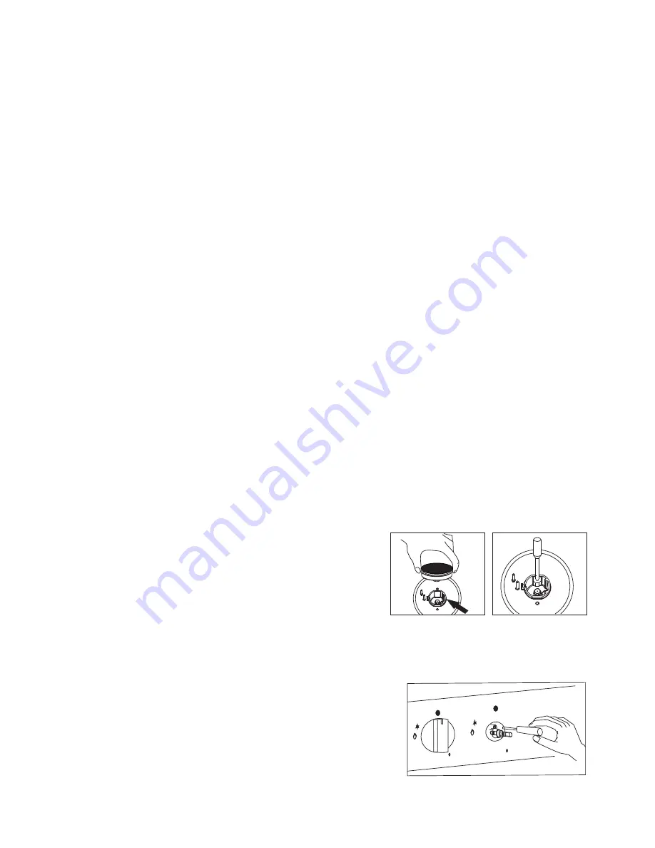
To adapt the appliance to a gas different from that 
for which it was set up (see gas type label inside 
the warming compartment door) proceed as follows: 

remove the grids 
remove the burners caps and burner heads 
with a 7 mm socket spanner unscrew and remove the injectors. 
replace the injectors with those supplied corresponding to the 

       gas available (see burner and injector characteristics Table) 

replace the various parts proceeding in reverse. 

 When converting from Natural Gas to 

 ensure that theNG regulator is removed and replaced with the Test 

Point Assembly. A gas regulator suitable for a supply pressure of  should be part of the gas tank supply and the 
test point pressure should be adjusted to 


Setting the minimum flame 
The flame on the small output is regulated by the factory. 
When the injectors have been replaced or there are special
mains pressure conditions, it may be necessary to regulate 
the minimum flame again. The operations necessary to set
the minimum flame are as following: 

light the burner ;
turn the knob to the minimum position ;
take out the knob (and gasket if there is one) ;

The flexible tube shall be fitted in such a way that it cannot come into 

contact with a moveable part of the housing unit (e.g. a drawer)and does not pass through any space 
susceptible of becoming congested

20mbar

LPG 

29mbar

29mbar

When converting from Universal LPG to Natural Gas ensure that the LPG test point is removed and replaced
with the CE Approved NG Regulator supplied in this kit. The test point pressure must be adjusted to 
20mbar with the largest burner operating on maximum flame.

When converting from Natural Gas  to Universal LPG  ensure that the NG regulator is removed and replaced
with the Test Point Assembly supplied in this kit. An CE Approved gas regulator suitablefor a supply pressure 
of 29mbar should be part of the gas tank supply and the test point pressure must be adjusted to 29mbar. 

LPG

the pressure according to the data plate.

l
l
l
l

l

l
l
l

Содержание EUR-FSG90

Страница 1: ...Model EUR FSGE60 ...

Страница 2: ...ould result in your warranty being invalid If you require any assistance please check with Eurotech Design Limited before installation is carried out We hope you enjoy your new appliance To view our f ull range of products visit www eurotechdesign co nz IMPORTANT NOTE New Zealand l aw dictates that this appliance m ust be i nstalled by an authorized installer The i nstallation of this appliance m ...

Страница 3: ...ypes of gas pag 7 Setting the minimum flame pag 7 Burner and injector characteristic table pag 8 Instructions for use Description of the main parts of the appliance pag 8 Ignition and operation of the burners pag 9 Advice on the use of gas burners pag 9 Oven function pag 10 Electronic programmer pag 11 Maintenance and cleaning pag 14 CAUTIONS pag 12 Instructions for cooking 2 ...

Страница 4: ...y water and rinse it l For any repairs always contact an authorised Eurotech Design Customer Service Centre and ask for original spare parts Repairs by untrained people can lead to damage l Keep packaging out of reach of children at all times l Always use oven gloves to remove and replace food in the oven Ensure that you support the grill pan when removing it from the oven l Don t let children sit...

Страница 5: ...opriate New Zealand standards and Regulatory requirements with particular reference to New Zealand El ectrical and or Gas i nstallation Standards Any attempt to i nstall this or any other E urotech Design products without authorized installation could result i n damage to the product and possible health hazards As well as result i n all associated warranties being null and void Eurotech Design Lim...

Страница 6: ...s of the cooker The screws should be fitted as follows Position the oven between the cupboards in it s final position then mark the location of the pilot hole inside the cupboard Refer to the diagram below for the location of the pilot hole Use 3 5mm diameter drill bit to drill the pilot hole through the cupboard and both sides of the cooker Before drilling check your measurements to ensure the pi...

Страница 7: ...llation and connection operations are carried out by qualified personnel complying with the local and general regulations in force Electrical features Oven light 25W Upper heating element 1950W Bottom heating element 1800W Grill heating element 2250W Circular heating element 1800W Ventilator motor 30W Cooling fan 11W This appliance shall be installed only by authorised persons and in accordance wi...

Страница 8: ...ct method of operation In case the appliance fails to operate correctly after all checks have been carried out refer to the authorised service provider in your area Adaptation to different types of gas To adapt the appliance to a gas different from that for which it was set up see gas type label inside the warming compartment door proceed as follows remove the grids remove the burners caps and bur...

Страница 9: ...on to the minimum position checking that the flame does not go out l for burners with safety valve make sure that the regulation obtained is sufficient to maintain heating of the thermocouple If it is not increase the minimum 8 l l LPG TO NG Use a thin blade screwdriver to turn the by pass screw located above left of the gas valve shaft as shown right Turn gently the by pass screw clockwise to the...

Страница 10: ...ventilated space Read the instructors before installing or using this appliance 2 The use of a gas cooking appliance results in the production of heat and moisture in the room in which it is installed Ensure that the kitchen is well ventilated keep natural ventilation holes open or install a mechanical ventilation device mechanical extractor hood 3 Prolonged intensive use of the appliance may call...

Страница 11: ...item is provided intervenes in case of accidental flame failure blocking the gas delivery e g air draughts spillage of liquids etc In any case the ignition device must not be actuated for longer than 15 seconds Should the ignition manoeuvre fail or should the burner be accidentally turned off immediately close the actuation knob and repeat the ignition after one minute at least Once the ignition h...

Страница 12: ...in the oven DELICATE COOKING THERMOSTAT SELECTOR SWITCH FROM 60 TO MAX Ideal for pastries and cakes with wet covering and little sugar and damp desserts in moulds Excellent results can also be achieved in completing cooking at the bottom and with dishes requiring heat in the Lower area in particular The plate is best inserted at bottom level TOP OVEN COOKING THERMOSTAT SELECTOR SWITCH FROM 60 TO M...

Страница 13: ... will flash After the roast is finished the roast operation process will be shut automatically Then AUTO flashing the alarm Rings The ring will stop by pressing the button B Set the time of ending 23hours 59minutes maximum Press the button to set the time of ending The oven starts immediately and AUTO will flash When the set time of ending comes the roast operation process will be shut automatical...

Страница 14: ...3 13 ...

Страница 15: ...he thermostat estinguishes Grill cooking Delete pre heat the oven for about 5 minutes During grill operation the heat comes from above it is based on the infrared radiation and is fit for low thickness meat and for toasts The meat and the fish to be grilled are to be slightly oiled and always placed on the grate this is to be arranged on the nearest or on the farthest guide from the grill element ...

Страница 16: ...5 5 5 5 5 5 5 5 5 5 5 Max Max Max Max Max Max Max Max Max 80 90 70 80 70 80 8 10 6 8 10 10 15 15 20 15 20 7 10 15 20 2 3 Fan Assisted Grill Grilled chicken Cuttlefish 1 5 1 5 3 3 5 5 200 200 55 60 30 35 With rotisserie where prevent Veal on the spit Chicken on the spit Chicken on the spit potatoes roasted Lamb on the spit 1 5 2 0 1 5 1 5 2 5 5 5 5 5 200 200 200 200 200 70 80 70 80 70 75 70 75 70 8...

Страница 17: ... steel pads or acids for cleaning To prevent lighting difficulties carefully clean the lighting spark plugs regularly ceramic and electrode Periodically if the knobs become difficult to turn contact a qualified engineer to lubricate the taps Contact a qualified engineer to deal with any other problems which may arise during use To keep the characteristics of brightness of the enamelled parts for a...

Страница 18: ... are in the OFF position and wait the grill elementcooling 2 Support the front of the grill element while you remove the knurled screw retaining the element 3 Lower the front of the element carefully to the rest position 4 When cleaning the oven make sure do not apply any forces to the grill element 5 When the cleaning is complete carefully remove any cleaning chemicals and water from the grill el...

Отзывы: