00048173.DOC, Version 1.3
13/15
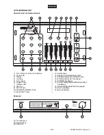
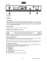
Rear panel:
21
22
23
21. DC Input
22. Sound input
23. DMX Out
5. SETUP
5.1 Installation
Install the unit on a plane surface or in your rack. For 483 mm rack installation (19"), 4 units (4 u) and the
optional Mouting frame for LED Operator 4 (no. 70064509) are required. You can fix the unit with four
screws M6 in the rack. When choosing the installation spot make sure that there is enough space around
the unit for ventilation or that heated air from the rack can be passed on to improve heat dissipation.
Steady overheating will damage your unit.
5.2 Sound-control
The sound-control works via the built-in microphone or RCA-input.
5.3 DMX-Connection between the devices
The wires must not come into contact with each other, otherwise
the fixtures will not work at all, or will not work properly.
Only use a stereo shielded cable and 3-pin XLR-plugs and connectors in order to connect the controller with
the fixture or one fixture with another.
Building a serial DMX-chain:
Connect the DMX-output of the DMX LED Operator 4 with the DMX-input of the nearest device. Always
connect one output with the input of the next fixture until all fixtures are connected.
Caution:
At the last fixture, the DMX-cable has to be terminated with a terminator. Solder a 120
resistor
between Signal (–) and Signal (+) into a 3-pin XLR-plug and plug it in the DMX-output of the last fixture.
5.4 Addressing the devices
The devices to be controlled need to be assigned the DMX starting address The starting address is defined
as the first channel from which the devices will respond to the controller.
Please assign the starting address to the devices as follows:
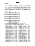
001 - LED PARCAN 1
006 - LED PARCAN 2
011 - LED PARCAN 3
016 - LED PARCAN 4
021 - LED KLS-200 RGB, also KLS-400/800/401/801/1001
036 - LED Bar RGB 252/10
049 - Smoke-machine
Now you can start operating them via your DMX LED Operator 4.


