EUCHNER CES-AP Series Скачать руководство пользователя страница 15

15

2112663-08-02/20 (Translation of the original operating instructions)

Operating Instructions

Non-Contact Safety Switch CES-AP-C01-…

EN

9.7.  Notes on operation with safe control systems

Please observe the following requirements for connection to safe control systems:


Ì

Use a common power supply for the control system and the connected safety switches. 


Ì

A pulsed power supply must not be used for U

B

. Tap the supply voltage directly from the power supply unit. If the power 

supply is connected to a terminal of a safe control system, this output must provide sufficient electrical current.


Ì

The safety outputs (OA and OB) can be connected to the safe inputs of a control system. Prerequisite: The input must 

be suitable for pulsed safety signals (OSSD signals, e.g. from light grids). The control system must tolerate test pulses 

on the input signals. This normally can be set up by parameter assignment in the control system. Observe the notes of 

the control system manufacturer. For the pulse duration of your safety switch, refer to chapter 

12. Technical data on 

page 19

.

A detailed example of connecting and setting the parameters of the control system is available for many devices at 

www.euchner.com, in the area 

Downloads/Applications/CES

. The features of the respective device are dealt with there in 

greater detail. 

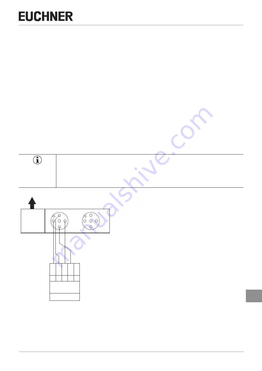
9.8.  Devices for direct connection to IP65 field modules

The version CES-AP-...-SB-... (M12, 5-pin; pin 5 not assigned) is optimized for connection to decentralized peripheral systems 

with M12 plug connector, such as the ET200pro series from Siemens. The devices are parameterized and connected like 

an OSSD (e.g. like light curtains).
If flying leads are used, connection to IP20 input and output modules (e.g. ET200s) is naturally also possible.

Important!

Observe the following notes prior to connection:


Ì

Parameter assignment must be performed for the input/output modules (see application example 

at www.euchner.com, in the area 

Downloads/Applications/CES

).


Ì

Additionally observe notes from the control system manufacturer where necessary.

CES-AP-...-SB-...

U

B

1

FO1A

2

0V

3

FO1B

4

S1: M12 plug-connector

(5-pin)

n.

c.

5

decentralized 

periphery

e.g. ET 200pro

PLC

DI

1

5

2

4

3

1 5

2

4

3

DO

Figure 4: 

Connection example for connection to decentralized peripheral systems

Содержание CES-AP Series

Страница 1: ...EN Operating Instructions Non Contact Safety Switch CES AP C01 Unicode Multicode ...

Страница 2: ...tching states 7 7 Changing the approach direction 8 8 Mounting 9 9 Electrical connection 10 9 1 Notes about 11 9 2 Safety in case of faults 11 9 3 Fuse protection for power supply 11 9 4 Requirements for connecting cables 11 9 5 Connector assignment of safety switch CES AP C01 12 9 6 Connection 13 9 7 Notes on operation with safe control systems 15 9 8 Devices for direct connection to IP65 field m...

Страница 3: ...ng distances 21 12 2 3 Typical actuating range 22 12 3 Technical data of actuator CES A BDA 18 23 12 3 1 Dimension drawing 23 12 3 2 Operating distances 23 12 3 3 Typical actuating range 24 12 4 Technical data of actuator CES A BPA 25 12 4 1 Dimension drawing 25 12 4 2 Operating distances 25 12 4 3 Typical actuating range 26 12 5 Technical data of actuator CES A BRN 27 12 5 1 Dimension drawing 27 ...

Страница 4: ...ment is available for download at www euchner com DANGER WARNING CAUTION Safety precautions Danger of death or severe injuries Warning about possible injuries Caution slight injuries possible NOTICE Important Notice about possible device damage Important information Tip Useful information 1 4 Supplementary documents The overall documentation for this device consists of the following documents Docu...

Страница 5: ...ceptions refer to EN ISO 12100 or relevant C standards Before the device is used a risk assessment must be performed on the machine e g in accordance with the following standards Ì EN ISO 13849 1 Ì EN ISO 12100 Ì IEC 62061 Correct use includes observing the relevant requirements for installation and operation particularly based on the following standards Ì EN ISO 13849 1 Ì EN ISO 14119 Ì EN 60204 ...

Страница 6: ...he safe function of the safeguard should be checked at suitable intervals as part of the maintenance schedule WARNING Danger to life due to improper installation or due to bypassing tampering Safety components perform a personnel protection function Ì Safety components must not be bypassed turned away removed or otherwise rendered ineffec tive On this topic pay attention in particular to the measu...

Страница 7: ...rating distance is reached power is supplied to the actuator by the switch and data are transferred If a permissible code is detected the safety outputs are switched on The safety outputs are turned off when the guard is opened In the event of a fault in the safety switch the safety outputs are switched off and the DIA LED illuminates red The occurrence of faults is detected at the latest on the n...

Страница 8: ...ace The plug connector can be realigned in 45 steps to change the direction of the cable outlet if elbow connectors are used 1 Remove the top part of the mounting base and push the bottom part of the mounting base off the read head 2 Unscrew the screws on the fastening bracket 3 Undo the read head from the fastening bracket and tilt the read head forward by 90 The active face is now pointing downw...

Страница 9: ...0 mm Ì If the actuator is installed flush the operating distances change as a function of the installation depth and the guard material Operating distance Actuator Operating distance Actuator Flush mounting Surface mounting Note the following points Ì Actuator and safety switch must be easily accessible for inspection and replacement Ì Actuator and safety switch must be fitted so that the front fa...

Страница 10: ...safety transformer according to IEC 61558 2 6 with limited output voltage in the event of a fault or by other equivalent isolation measures PELV Ì All electrical outputs must have an adequate protective circuit for inductive loads The outputs must be protected with a free wheeling diode for this purpose RC interference suppression units must not be used Ì Power devices which are a powerful source ...

Страница 11: ... The operating voltage UB is reverse polarity protected Ì The safety outputs are short circuit proof Ì A short circuit between the safety outputs is detected by the switch Ì A short circuit in the cable can be excluded by laying the cable with protection 9 3 Fuse protection for power supply The power supply must be provided with fuse protection depending on the number of switches and the current r...

Страница 12: ... OA OB DIA RST 1 3 2 4 5 UB 0V OA OB DIA 1 3 2 4 5 UB 0V OA OB n c 8 pin 5 pin 8 2 7 6 1 3 4 5 UB 0V n c n c OA OB DIA RST 1 3 2 4 5 UB 0V OA OB DIA 1 3 2 4 5 UB 0V OA OB n c 8 pin 5 pin 5 pin pin 5 not used Figure 1 Connector assignment of safety switch CES AP C01 Pin Plug connector Designation Description Conductor coloring 8 pin 5 pin 5 pin pin 5 not used 1 n c Not used WH 2 1 1 UB Power supply...

Страница 13: ...tion Ì To ensure safety both safety outputs OA and OB must always be evaluated Important The example shows only an excerpt that is relevant for the connection of the CES system The example illustrated here does not show complete system planning The user is responsible for safe integration into the overall system Detailed application examples can be found at www euchner com Simply enter the order n...

Страница 14: ...AP C01 14 Translation of the original operating instructions 2112663 08 02 20 24 V DC GND F1 Connected load Safety Outputs Monitoring Output Read Head B4 UB 2 7 0V 5 DIA 3 OA 4 OB RST 8 NC 6 NC 1 CES S1 Figure 3 Connection example CES AP with reset button ...

Страница 15: ...o chapter 12 Technical data on page 19 A detailed example of connecting and setting the parameters of the control system is available for many devices at www euchner com in the area Downloads Applications CES The features of the respective device are dealt with there in greater detail 9 8 Devices for direct connection to IP65 field modules The version CES AP SB M12 5 pin pin 5 not assigned is opti...

Страница 16: ...ch can be operated only with the last actuator taught in Ì The number of teach in operations is unlimited Ì If the switch detects the actuator that was most recently taught in when in the teach in standby state this state is ended immediately and the switch changes to normal operation Ì If the actuator to be taught in is within the actuating range for less than 60 s it will not be activat ed and t...

Страница 17: ...function test After installation and any fault the safety function must be fully checked Proceed as follows 1 Switch on operating voltage The machine must not start automatically The safety switch carries out a self test The green STATE LED then flashes at regular intervals 2 Close all guards The machine must not start automatically The green STATE LED illuminates continuously 3 Enable operation i...

Страница 18: ...wer up closed off 1 Hz Teach in operation X off Positive acknowledgment after completion of teach in operation Fault display closed off 3 x Defective actuator e g fault in code or code not readable X off 4 x Output fault e g short circuits loss of switching ability X off 5 x Internal fault e g component faulty data error Key to symbols LED not illuminated LED illuminated 10 Hz 8 s LED flashes for ...

Страница 19: ...U OA UB 1 5 UB V DC HIGH U OB LOW U OA U OB 0 1 Switching current per safety output 1 400 mA Utilization category acc to EN IEC 60947 5 2 DC 13 24 V 400 mA Caution Outputs must be protected by a free wheeling diode in the case of inductive loads Off state current Ir 2 0 25 mA Monitoring output DIA 1 p switching short circuit proof Output voltage 0 8 x UB UB V DC Max load 200 mA Rated insulation vo...

Страница 20: ...ing range the safety outputs OA and OB are deactivated at the latest after the risk time Discrepancy time The safety outputs OA and OB switch with a slight time offset They have the same signal state no later than after the discrepancy time Test pulses at the safety outputs The device generates its own test pulses on the output lines OA OB A downstream control system must tolerate these test pulse...

Страница 21: ...ion IP65 IP67 IP69 IP69K Installation orientation Active face opposite read head Power supply Inductive via read head 12 2 1 Dimension drawing CES A B 071840 25 ø8 ø4 5 42 32 0 1 12 4 6 Active face Active face NOTICE 2 safety screws M4x14 included 12 2 2 Operating distances Actuating range for center offset m 0 1 Parameter Value Unit min typ max Operating distance 18 mm Assured operating distance ...

Страница 22: ... Typical actuating range only in combination with actuator CES A BBA X 2 5 1 5 2 0 1 0 5 20 25 30 5 10 15 30 30 30 25 20 15 10 5 Y Z For a side approach direction for the actuator and safety switch a minimum distance of s 4 mm must be maintained so that the actuating range of the side lobes is not entered Figure 5 Typical actuating range ...

Страница 23: ...s 18 x 9 mm Weight 0 003 kg Ambient temperature 25 70 C Degree of protection IP65 IP67 Installation orientation Active face opposite read head Power supply Inductive via read head 12 3 1 Dimension drawing 18 9 4 4 7 Active face Active face NOTICE 1 safety screw M4x14 included 12 3 2 Operating distances Actuating range for center offset m 0 1 Parameter Value Unit min typ max Operating distance 19 m...

Страница 24: ...tuating range only in combination with actuator CES A BDA 18 on surface mounting Y 30 25 20 15 10 5 30 30 25 30 Z 15 20 25 10 5 X 2 5 2 0 1 5 1 0 5 For a side approach direction for the actuator and read head a minimum distance of s 8 mm must be maintained so that the actuating range of the side lobes is not entered Figure 6 Typical actuating range ...

Страница 25: ...IP67 IP69 IP69K Installation orientation Active face opposite read head Power supply Inductive via read head 12 4 1 Dimension drawing 30 0 1 40 0 25 0 CES A BPA 098775 IP67 CD 10 4 Ø 5 2 Active face Active face NOTICE 2 safety screws M5x10 included 12 4 2 Operating distances Actuating range for center offset m 0 1 Parameter Value Unit min typ max Operating distance 22 mm Assured operating distance...

Страница 26: ...nge only in combination with actuator CES A BPA on surface mounting 45 40 35 30 25 20 15 10 45 5 Z Y X 5 10 15 20 25 30 35 40 45 45 40 45 35 30 25 20 15 10 5 For a side approach direction for the actuator and read head a minimum distance of s 6 mm must be maintained so that the actuating range of the side lobes is not entered Figure 7 Typical actuating range ...

Страница 27: ...f protection IP67 Installation orientation Active face opposite read head Power supply Inductive via read head 12 5 1 Dimension drawing Active face Active face 40 80 10 3 5 5 17 11 17 11 15 8 5 NOTICE 2 safety screws M5x16 included 12 5 2 Operating distances Actuating range for center offset m 0 1 Parameter Value Unit min typ max Operating distance 27 mm Assured operating distance sao 20 Switching...

Страница 28: ...ctuator CES A BRN on surface mounting on metal 5 2 0 2 5 3 0 3 5 Z X 5 15 20 50 45 40 35 30 25 50 Y 5 10 15 20 25 30 35 40 45 50 55 60 65 10 5 15 25 30 40 45 50 55 60 65 1 5 1 0 10 20 35 For a side approach direction for the actuator and read head a minimum distance of s 6 mm must be maintained so that the actuating range of the side lobes is not entered Figure 8 Typical actuating range ...

Страница 29: ...ies or spare parts that can be ordered from EUCHNER may be replaced Regular inspection of the following is necessary to ensure trouble free long term operation Ì Check the switching function see chapter 10 3 Functional check on page 17 Ì Check the secure mounting of the devices and the connections Ì Check for soiling No servicing is required Repairs to the device are only allowed to be made by the...

Страница 30: ...Operating Instructions Non Contact Safety Switch CES AP C01 30 Translation of the original operating instructions 2112663 08 02 20 16 Declaration of conformity ...

Страница 31: ...31 2112663 08 02 20 Translation of the original operating instructions Operating Instructions Non Contact Safety Switch CES AP C01 EN ...

Страница 32: ...uchner com Edition 2112663 08 02 20 Title Operating Instructions Non Contact Safety Switch CES AP C01 Translation of the original operating instructions Copyright EUCHNER GmbH Co KG 02 2020 Subject to technical modifications no responsibility is accept ed for the accuracy of this information ...

Отзывы: