


Operating instructions
Non-Contact Safety System CES-A-UBA-01/CES-A-UBA-01B
14
(Translation of the original operating instructions) 2097097-17-08/20
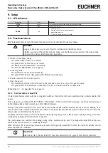
9. Setup
9.1. LED indicators
Designation
Color
Meaning
STATE
green
Status indication (multifunction display using flashing modes)
OUT
yellow
Safety circuit closed
ERROR
red
Ì
Operating fault or
Ì
External fault (fault in the feedback loop) or
Ì
Internal device fault or
Ì
TST input activated (function test active)
9.2. Functional check
After installation and any fault, the safety function must be fully checked. Proceed as follows:
WARNING
Danger of fatal injury as a result of faults in installation and functional check.
Ì
Before carrying out the functional check, make sure that there are no persons in the danger zone.
Ì
Observe the valid accident prevention regulations.
1. Switch on operating voltage.
-The safety switch carries out a self-test.
The green STATE LED flashes up to 3 times.
The STATE LED then illuminates continuously.
The OUT and ERROR LEDs do not light up.
2. Close all guards.
-The machine must not start automatically.
-The green STATE LED and the yellow OUT LED light up continuously.
3. Enable operation in the control system.
4. Open the guard.
-The machine must switch off and it must not be possible to start it as long as the guard is open.
-The green STATE LED illuminates continuously; the OUT and ERROR LEDs do not illuminate.
Repeat steps 2 … 4 separately for each guard.
9.2.1. Self-test with test input TST
On electromechanical safety switches or magnetic switches, the function test can be performed by cyclically opening the
guard.
From category 2 according to EN ISO 13849-1, EN 60204-1 : 1997 (section 9.4.2.4) requires a function test performed
on the entire safety system on start-up or after defined intervals.
Testing of the internal function of the unit is not necessary because the device monitors itself in real time. Welding of an
output contact (relay output) is detected by the device at the latest the next time the guard is opened. A short circuit in the
output cable is not detected by the device.
In addition, the entire safety circuit can be tested without opening the guard. For this purpose, opening of the guard can be
simulated by applying 24 V DC to the test input TST.
The safety outputs are switched off, enabling testing of the complete safety circuit. The diagnostic output ERR on the eval-
uation unit is also set HIGH as a monitoring function.
When test input TST is reset, the evaluation unit resets the diagnostic output ERR to LOW, the red LED switches off and
normal operation is continued.
Important!
After the self-test, the test input TST must be connected to 0 V again or must be disconnected.


