


3
Camera
Quick start
guide
CD
Template
Screws
Water-proof
cap
Screwdriver
EN
Before use this product
- Before operation, we strongly advise users to read this manual and keep it properly for using later.
- This is product instructions not quality warranty. We may reserve the rights of amending the typographical errors, inconsisten-
cies with the latest version, software upgrades and product improvements, interpretation and modification. These changes will
be published in the latest version without special notification.
- When this product is in use, the relevant contents of Microsoft, Apple and Google will be involved in. The pictures and scre-
enshots in this manual are only used to explain the usage of our product. The ownerships of trademarks, logos and other
intellectual properties related to Microsoft, Apple and Google belong to the above-mentioned companies.
1 Introduction
Summarization
This IP-CAMERA (short for IP-CAM) is designed for high performance CCTV solutions. It adopts state of the art video proces-
sing chips. It utilizes most advanced technologies, such as video encoding and decoding technology, complies with the TCP/IP
protocol, SoC, etc to ensure this system more stable and reliable. This unit consists of two parts: the IP-CAM device and central
management software (short for CMS). The CMS centralizes all devices together via internet or LAN and establishes a sound
surveillance system to realize unified management and remote operation to all devices in one network.
This product is widely used in banks, telecommunication systems, electricity power departments, law systems, factories, sto-
rehouses, uptowns, etc. In addition, it is also an ideal choice for surveillance sites with middle or high risks.
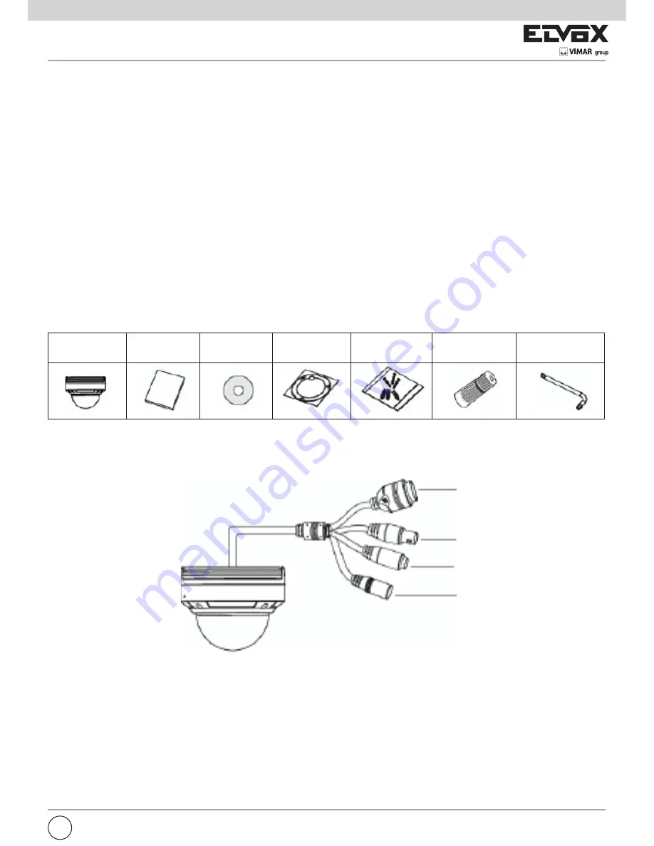
Check Package Content
Connection
Some models support 10m~20m IR distance; some hasn’t infrared lights that cannot support IR night vision. Please take the real
object as standard. The below figures will introduce the appearance and function of interfaces.
CVBS
Output: connect to an input analog device (monitor)
DC12V:
connect to power supply
LAN:
network port (some models support PoE power supply)
2 Installation
2.1 Installation
The installation steps of Dome Camera are as follows:
Step 1- Loosen the screws with a hexagonal screwdriver and take down the back box as shown in the following left picutre.
Step 2- Paste the plotting sheet on the ceiling. Drill four holes and instert spiles in the ceiling as per the sheet. Use the screws
to fix the bottomboard on the ceiling.
1-LAN
2-CVBS
3-MIC
4-DC 12V


