


Model 5506 Mid-Size Chamber
–
Operating Manual
D01332 Revision B - 2021-03-16 - Page
7
of
20
Part 2: Connection and Setup of the System
NOTE: Your equipment may look different from these photos, or items may not be included.
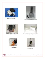
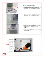
Step 1
–
Ports and Gloves
If Glove Ports are included, verify that the gloves
are smoothly wrapped onto the ports with thumbs
facing upward, and the clamps are firmly holding
them in place.
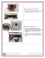
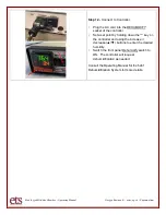
Step 2
–
Controller
– 5000 series
•
Place the controller in a convenient location, and
switch all front panel switches to the OFF (0)
position.
•
Turn controller around to reveal the connections.
•
Switch the POWER switch to OFF (0).
•
Plug the 556 sensor into the SENSOR jack
•
Connect the AC power cord to POWER IN, and plug
the cord into AC Power.
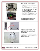
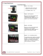
Step 3
–
Sensor - Model 556
•
Ensure that the sensor and its cable are firmly
connected together.
•
Loosen
the ¾” fitting located to the left of the
chamber door and insert the sensor from outside.
•
Position the sensor as shown and tighten the fitting
nut by hand only - Do not use tools