background image


ETON America, LLC 

Oil Pump Flow Adjustment  

all Oil Injected two cycle Engines 

Service Bulletin


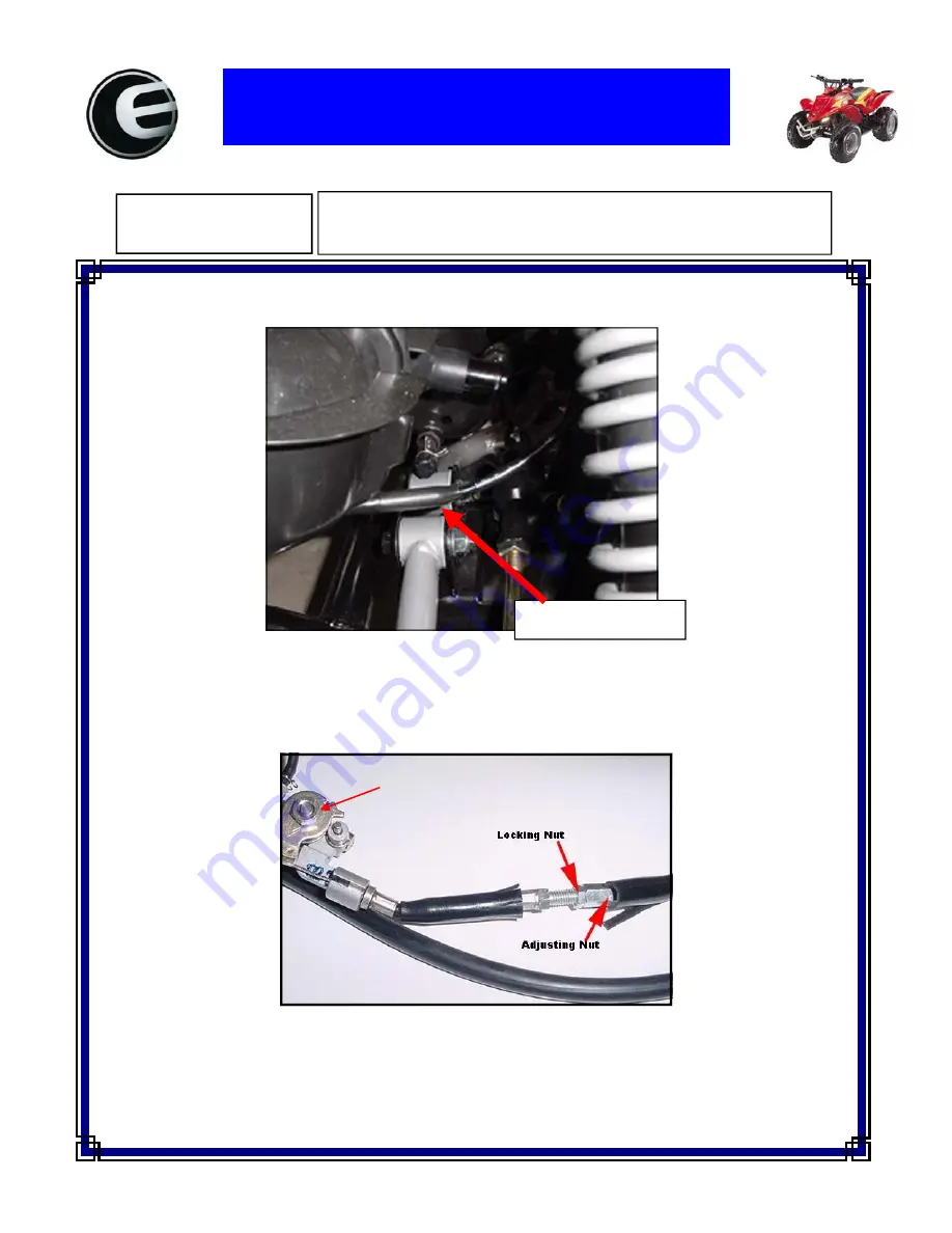
To adjust the oil pump flow on a two cycle oil injected engine you must adjust the oil pump cable length. . The 
Oil pump cable is located on the right hand side of the engine just above the (RH) A-arm 

Bulletin No:      

0033  

           Date:  

04/01/2004


Oil Pump Cable Location 

To reduce the oil flow you must lengthen the cable by loosening the lock nut and turning the adjusting nut 
counter clockwise  then retighten the locking nut. To increase the oil flow you would shorten the cable by 
turning the adjusting nut clockwise. 

Oil Pump 

www.Get2itParts.com

www.Get2itParts.com

www.Get2itParts.com

Содержание Rascal IXL-40

Страница 1: ...ETON America 40cc Service Manual Covering Rascal IXL 40 Viper Jr RXL 40 Viper 40E RXL 40E w w G e t 2 i t P a r t s c o m w w w G e t 2 i t P a r t s c o m w w w G e t 2 i t P a r t s c...

Страница 2: ...w w G e t 2 i t P a r t s c o m w w w G e t 2 i t P a r t s c o m w w w G e t 2 i t P a r t s c...

Страница 3: ...e Combustion system 6 Pull Electric Starter 7 Transmission 8 Front Wheels and Steering 9 Rear Wheels and Drive System 10 Body Cover Exhaust System 11 Electrical System 12 Trouble Shooting Chart 13 RXL...

Страница 4: ...w w G e t 2 i t P a r t s c o m w w w G e t 2 i t P a r t s c o m w w w G e t 2 i t P a r t s c...

Страница 5: ...ntact flush thoroughly with water Seek medical attention if electrolyte gets in the eyes 1 2 NOTES All information illustrations directions and specifications included in this publication are based on...

Страница 6: ...eed automatic clutch CHASSIS Overall Length 1160mm 45 7inch Overall Width 650mm 25 6inch Overall Height 727mm 28 6inch Seat Height 540mm 21 3inch Wheel base 728mm 28 7inch Ground Clearance 75mm 3 0inc...

Страница 7: ...is stamped on a plate attached to the front of the frame The Engine serial number is stamped on the left side of the crankcase 1 3 Engine Number Serial Number w w G e t 2 i t P a r t s c o m w w w G...

Страница 8: ...dlebar upper holder bolt 4 6 mm 10 14 7 10 Steering shaft nut 1 14 mm 50 60 37 44 Steering shaft bushing holder nut 2 8 mm 24 30 17 22 Tie rod lock nut 4 10 mm 35 43 25 32 King pin nut 2 10 mm 30 40 2...

Страница 9: ...D TIRES 2 12 STEERING SYSTEM 2 13 TOE IN 2 14 GEAR OIL 2 1 MAINTENANCE DATA SPECIFICATIONS SPARK PLUG GAP RECOMMENDED SPARK PLUGS THROTTLE LEVER FREE PLAY IDLE SPEED BRAKE LEVER FREE PLAY DRIVE CHAIN...

Страница 10: ...I Inspect and Clean Adjust Lubricate or Replace if necessary C Clean L Lubricate R Replace 2 3 FUEL LINES Inspect the fuel lines for deterioration damage or leakage and replace if necessary 2 4 THROTT...

Страница 11: ...air cleaner from carburetor 2 Disassemble the air cleaner cover and body 3 Remove the air cleaner element and screen 4 Wash the element in non flammable or high flash point solvent squeeze out the sol...

Страница 12: ...sher and replace with a new one if damaged 2 8 IDLE SPEED 1 Inspect and adjust the idle speed after all other engine maintenance has been performed and is within specifications The engine must be warm...

Страница 13: ...e drive chain with kerosene and wipe it dry Inspect the drive chain for possible wear or damage Replace the chain if it is worn excessively or damaged Inspect the sprocket teeth If it shows signs of e...

Страница 14: ...cm2 2 12 STEERING SYSTEM Check the free play of the steering shaft with the front wheels pointed straight ahead If there is excessive play inspect the tie rod kingpin bushing and ball joint 2 13 TOE I...

Страница 15: ...length of the tie rods equally by turning the tie rod while holding the ball joint Tighten the lock nuts Torque 35 43 N m 2 14 GEAR OIL Gear oil needs to be changed every year There is a gear oil Drai...

Страница 16: ...ve the chain protection cover Remove the drive chain retaining clip and master link and remove the drive chain Remove the lower engine hanger nuts and the lower mission case hanger bolt at the right s...

Страница 17: ...tank cap breathing hole clogged Carburetor fuel jet clogged Fuel tank cap breathing hole clogged Fuel filter clogged Fuel flows restricted Float level in carburetor too low Float needle valve in carbu...

Страница 18: ...cable assembly The carburetor top cannot be separated from the assembly without causing damage to the cable Never kink or twist control cables They will not operate smoothly and may stick if they are...

Страница 19: ...nings with compressed air Inspect the needle jet and main jet Check each part for wear or damage Clean the passages and jets with compressed air 4 6 FLOATS FLOAT VALVE AND JETS ASSEMBLY NOTE Handle al...

Страница 20: ...le valve and secure it with the needle clip retainer Install the spring and throttle valve Align the throttle valve slit with the locating pin in the carburetor body and install the carburetor top ont...

Страница 21: ...ner and carburetor Remove the Ignition Coil assembly Remove the cylinder shroud rubber cap and shroud Remove the spark plug Remove the inlet pipe insulator and gasket 5 1 w w G e t 2 i t P a r t s c o...

Страница 22: ...rmine the taper TAPER LIMIT 0 01mm Calculate the cylinder out of round at three levels in the X and Y axis Take the maximum reading to determine the out of round Out OF ROUND 0 10mm 5 3 PISTON REMOVAL...

Страница 23: ...the piston outer diameter at 10mm up from the skirts bottom SERVICE LIMIT 39 9 mm Measure the piston pin outer diameter PIN BORE SERVICE LIMIT 10 04 mm Measure the piston pin bore PIN OUT DIAMETER SE...

Страница 24: ...be on the grooves After installation the rings should be free to rotate in the ring grooves 5 5 PISTON INSTALLATION Install the connecting 2 bearing and washer Install the piston with its mark on the...

Страница 25: ...crankcase surface Install a new gasket Coat the cylinder bore and piston rings with engine oil and install the cylinder NOTE Avoid damaging piston rings during installation Install the spark plug and...

Страница 26: ...ful to remove the reel and prevent the spring from flicking away Inspect the spring for wear or damage and replace if necessary 6 2 CRANKCASE DISASSEMBLY Remove the clutch one way and L crankcase plat...

Страница 27: ...oil assembly Remove the A C generator assembly Disassemble the right crankcase and left crankcase Remove the crankshaft composition 6 2 w w G e t 2 i t P a r t s c o m w w w G e t 2 i t P a r t s c o...

Страница 28: ...ket material and install the dowel pins and a new gasket Assemble the right crankcase and left crankcase 6 4 RIGHT CRANKCASE ASSEMBLY Install the A C generator assembly Install the holder 6 3 w w G e...

Страница 29: ...e the right crankcase and right crankcase cover 6 5 LEFT CRANKCASE ASSEMBLY Install the L crankcase plate and clutch one way Install the left crankcase cover 6 4 w w G e t 2 i t P a r t s c o m w w w...

Страница 30: ...clutch weight set from the A C generator assembly Inspect and clean the clutch shoes before reinstalling 6 8 INSPECTION Check the removed parts for wear or damage Measure the relaxed length of the sp...

Страница 31: ...h weight set on the A C generator assembly 6 10 CLUTCH OUTER INSTALLATION Install the clutch outer composition on the gearbox Assemble the gearbox and right crankcase cover 6 6 w w G e t 2 i t P a r t...

Страница 32: ...rd Remove the gearbox cover while tapping the cases at several locations with a rubber mallet or soft hammer Remove the dowel pins and gasket GEAR SHAFT DISASSEMBLY Remove the counter gear composition...

Страница 33: ...of the bearings fit tightly in the gear box Replace the bearings if they are abnormal 7 3 GEAR SHAFT ASSEMBLY Assemble the drive final idle and counter gear compo sitions in the reverse order of disa...

Страница 34: ...box cover Install one clamp pulser cord and tighten all the box bolts Install the sprocket and fixing plate on the final gear shaft 7 3 w w G e t 2 i t P a r t s c o m w w w G e t 2 i t P a r t s c o...

Страница 35: ...w w G e t 2 i t P a r t s c o m w w w G e t 2 i t P a r t s c o m w w w G e t 2 i t P a r t s c...

Страница 36: ...installed incorrectly Worn swing arm pivot bushings Shock absorber damper binding Loose front suspension fasteners Faulty pivot bearing Bent shock absorber Bent shock absorber swing rod Faulty front...

Страница 37: ...ar on the lower holders Make sure the handlebar punch marks align with the top of the lower handlebar holders Install the upper handlebar holders with the L or R marks facing forward Tighten the forwa...

Страница 38: ...ound by placing a block under the frame Remove the front wheel nuts washer and wheels INSTALLATION Install and tighten the four wheel nuts Torque 55 65 N m 35 45 ft lbs Remember put a cotter pin in th...

Страница 39: ...NSPECTION Inspect the kingpin for damage or cracks Measure the kingpin outer diameter Upper minimum limit 15 40 mm Lower minimum limit 16 90 mm KINGPIN BUSHING INSPECTION There are two bushings in the...

Страница 40: ...steering shaft Remove the bushing from the shaft Inspect the bushing for damage or wear replace if nec essary Measure the bushing inner diameter Maximum limit 22 8 mm STEERING SHAFT INSPECTION Inspect...

Страница 41: ...lbs Install the steering shaft nut and tighten it This nut is under this steering shaft Torque 50 60 N m 35 45 ft lbs INSTALLATION OF KINGPIN Use grease to lubricate the kingpin lower dust seal lips b...

Страница 42: ...9 REAR WHEEL SYSTEM 9 1 THE PARTS DRAWING OF REAR WHEEL SYSTEM 9 1 w w G e t 2 i t P a r t s c o m w w w G e t 2 i t P a r t s c o m w w w G e t 2 i t P a r t s c...

Страница 43: ...earings are worn Faulty tires Rear axle bearing holder is faulty Shock absorber damper binding Loose front suspension fasteners Faulty pivot bearing Bent shock absorber Bent shock absorber swing rod F...

Страница 44: ...the brake drum cover Remove the axle collar and brake drum Check the brake lining thickness The minimum limit is 2 0 mm Check the brake drum for damage Replace if necessary Check the brake drum inner...

Страница 45: ...ble the chain retaining clip and master link Disassemble the driven sprocket axle and sprocket collar Check the driven sprocket for damage or wear Let the rear axle lie on V blocks and check the run o...

Страница 46: ...mble the drive chain on the driven sprocket Assemble the master link and retaining clip Note the retaining clip direction Install the drive chain cover Assemble the chain under cover 9 5 REAR BRAKE AN...

Страница 47: ...justers Install the brake shoes and springs to their original positions Assemble the brake drum axle collar and brake drum cover Assemble the wheel Tighten the rear axle nut with 60 80 N m 44 60 ft lb...

Страница 48: ...BODY COVER EXHAUST MUFFLER 10 FENDERS AND EXHAUST PIPE 10 1 FENDERS DRAWING 9 bolts w w G e t 2 i t P a r t s c o m w w w G e t 2 i t P a r t s c o m w w w G e t 2 i t P a r t s c...

Страница 49: ...center frame See picture Remove the two bolts which attach the body cover on the rear frame The body cover can now be removed from the frame 10 3 FOOTREST COVER REMOVAL Remove the seat see chapter 10...

Страница 50: ...the unit Inspect the exhaust system for rust or holes Replace the exhaust pipe and muffler system if damaged or leaking Clean the manifold gasket material from the engine and exhaust manifold before...

Страница 51: ...d spark plug Faulty ignition coil Faulty CDI unit Faulty engine stop switch Ignition primary circuit Loose contact at terminals Faulty plug cap Faulty plug Faulty ignition coil Faulty engine stop swit...

Страница 52: ...CONTROLLER CONTROLLER RECEIVER The controller has a maximum effective distance of 30 ft To maintain the effective distance of the controller the batteries must be kept at or near full charge Check ba...

Страница 53: ...11 5 WIRING DIAGRAMS FOR RXL40 FOR IXL40 11 3 w w G e t 2 i t P a r t s c o m w w w G e t 2 i t P a r t s c o m w w w G e t 2 i t P a r t s c...

Страница 54: ...FOR RXL 40E 11 4 w w G e t 2 i t P a r t s c o m w w w G e t 2 i t P a r t s c o m w w w G e t 2 i t P a r t s c...

Страница 55: ...ed Auto Choke Power Wire not connected Improperly Adjusted Air Screw Improper Ignition Timing Adjustment Fuel Air mixture ratio is too lean Carburetor Flooded Improperly Adjusted Air Screw Fuel Air mi...

Страница 56: ...C D I Unit Faulty Engine stop Switch Poor connection Broken or Shorted Wire Broken or Shorted Ignition Coil Broken or Shorted Spark Plug Wire Faulty Pulse Generator Check for Intake Manifold Leak Che...

Страница 57: ...e Clogged Fuel Filter Jets Clogged Clean with High Pressure Air Clean or Replace Filter Screen Check Carburetor Jets Check Ignition Timing Check Fuel Flow at Carburetor Air Cleaner O K O K O K N G N G...

Страница 58: ...combustion chamber Wrong Fuel Type Fuel Air mixture ratio to lean Used poor quality Fuel Worn Piston and Cylinder Fuel Air mixture ratio to lean Wrong Fuel Type Ignition Timing to Advanced Excessive C...

Страница 59: ...cessive Wheel Bearing Play Bent Swing Arm Bent Frame Excessive Wear of Swing arm Bushing Bent Tie Rod Incorrect Tie Rod Adjustment Incorrect Rear Tire pressure Improper Wheel Alignment Bent Frame Bent...

Страница 60: ...tarts Problem Solved Test the brake switch The brake switch is a normal open switch Disconnect the two leads on the switch and test continuity with a multi meter With brake lever applied there should...

Страница 61: ...ix for 40cc Engine starts Fuel petcock in ON position Turn fuel petcock to ON position Engine starts Fuel line clogged Clear fuel lines Engine starts Fuel filter clogged Clean replace fuel filter Engi...

Страница 62: ...Engine starts Plug gap set to 0 036 Set gap to 0 036 Engine starts Test for spark at the spark plug Remove the plug and place it in the ignition cap and ground against the motor Press the starter butt...

Страница 63: ...s with a multi meter Current detected Replace ignition switch Depress the left hand brake Check the rear lights Rear lights do not light when brake depressed or stay on when released Replace rear brak...

Страница 64: ...No Engine Does Not Start Check the keyway on the flywheel Key is sheared Replace the key Engine starts Replace CDI Box Continue to 12 7 6 Problem Solved 12 10 w w G e t 2 i t P a r t s c o m w w w G e...

Страница 65: ...Does Not Start Engine compression below 95PSI Rebuild top end Engine starts Contact ETON Technical Service at 864 278 9585 EXT 114 Problem unsolved Problem Solved 12 11 w w G e t 2 i t P a r t s c o m...

Страница 66: ...the starter motor remove the two 8mm bolts as shown in the picture Cap can be removed from starter motor to gain access to the armature and the brushes Clean and inspect before replacing the starter m...

Страница 67: ...he AC generator also should be cleaned and inspected as well as the charging coils To test output voltage motor must be started or turning Voltage should be 12V Output voltage coming from the AC gener...

Страница 68: ...VEHICLES ARE MAINTANCE FREE PROPER SERVICE PROCEDURES ARE AS FOLLOWS 1 FILL BATTERY WITH BATTERY PACK SUPPLIED 2 REMOVE FUNNEL AND LET BATTERY STAND WITH CAP OFF FOR AT LEAST 1 HR 3 ALL FLUID IN BATTE...

Страница 69: ...ter will also reduce plug fouling concerns and is a more efficient way to adjust speed for beginning riders Adjust the CDI speed limiter to the desired speed and power and then adjust the throttle sto...

Страница 70: ...sive amount of research into the proper fuel oil mixture for the Rascal IXL 40 we have deter mined the proper fuel oil mixture ratio to be 50 1 Our research showed that with today s oil technologies a...

Страница 71: ...has been disengaged or connection wire unplugged 2 Engine Stop switch has not been turn to the run position 3 Fouled spark plugs due to not switching to a 50 1 fuel oil ratio as stated in Tech Bullet...

Страница 72: ...ded periods of time 2 Viper 50M 50 70 90 90R Your first tank of fuel should be a pre mixture of fuel and oil at a 50 1 ratio This will insure that the oil pump system has been primed and bled of air t...

Страница 73: ...et tube see photo below The only differences in the carburetor kits are the needle and seat assembly See pictures below to select the correct kit Kit 811276 Needle and seat assembly Kit 810463 Needle...

Страница 74: ...Pull the rubber cap from the switch and the bike should stop If it doesn t check the connections for your bike as shown in the pictures Bulletin No 0031 Date 07 20 04 Switch color codes 40E 50M 70 90R...

Страница 75: ...he spark arrestor with a pair of needle nose pliers figure 3 Then clean the screen or replace the element part 811008 Symptoms of a dirty spark arrestor 1 Loss of power or no power 2 Bad throttle resp...

Страница 76: ...e of the engine just above the RH A arm Bulletin No 0033 Date 04 01 2004 Oil Pump Cable Location To reduce the oil flow you must lengthen the cable by loosening the lock nut and turning the adjusting...

Страница 77: ...tal type meter produces to many inaccurate readings Bulletin No SB 0042 Date 05 01 2006 I G N E TON PCi n BLACK WHITE RED BLACK B BLACK GND WHITE BLUE RXL 40E C0410 UE8 0000 Electric resistance specif...

Страница 78: ...w w G e t 2 i t P a r t s c o m w w w G e t 2 i t P a r t s c o m w w w G e t 2 i t P a r t s c...

Отзывы: