background image


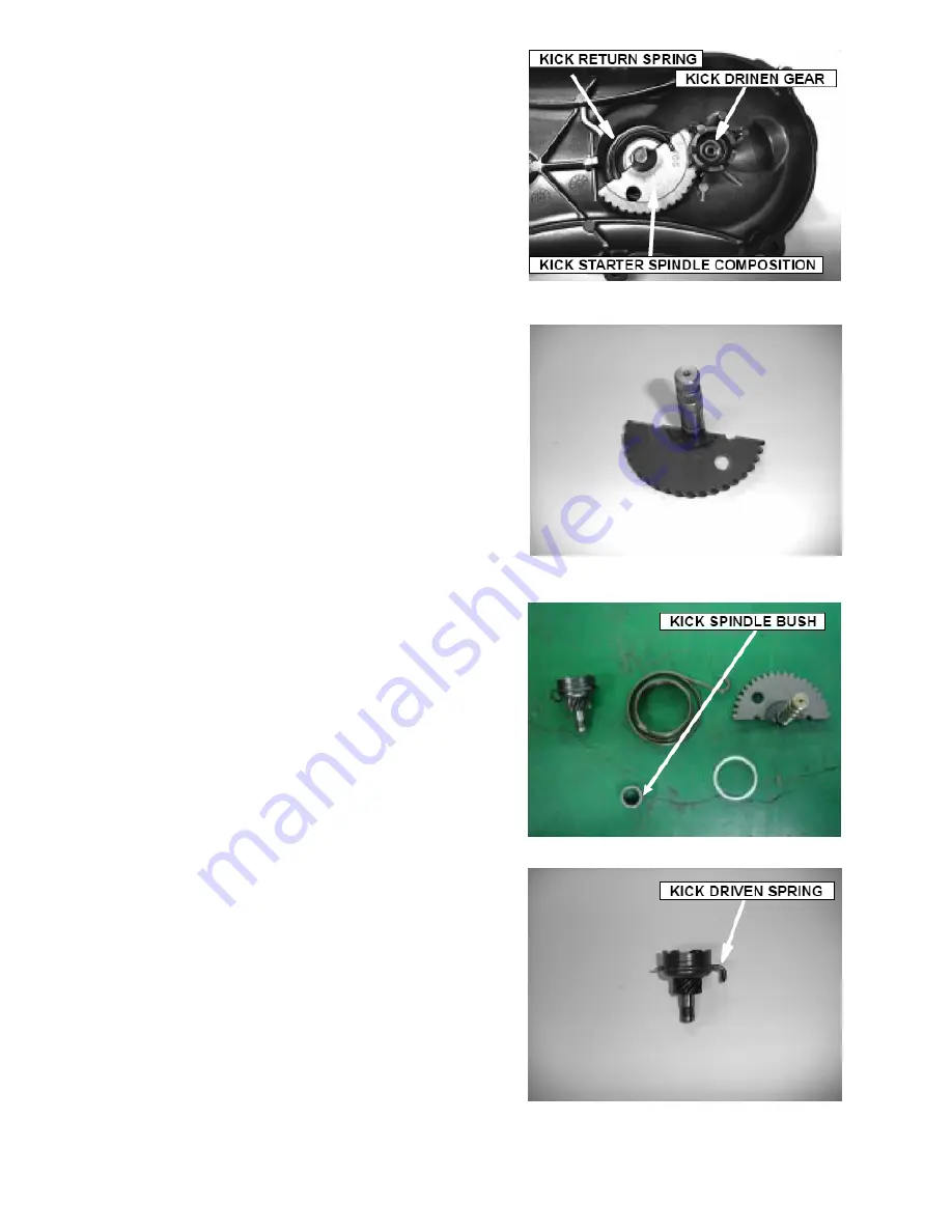
Rotate the kick-starter spindle composition to remove 
the kick driven gear and spring. 
Remove the kick-starter spindle composition and return 
spring. 
Remove the kick spindle bush. 

INSPECTION 

Inspect the kick starter spindle composition for wear or 
damage. 

Inspect the kick return spring for fatigue or damage. 
Inspect the kick spindle bush for wear or damage. 

Inspect the kick driven gear and spring for wear or 
damage. 

Содержание Matrix R4-150

Страница 1: ...ETON America MATRIX R4 150 Service Manual Covers MATRIX R4 150 PN2I SCOOTER ...

Страница 2: ... 2 TROUBLESHOOTING 28 5 3 ENGINE OIL LEVEL 28 5 4 ENGINE OIL FILTER CHANGE 28 5 5 OIL PUMP REMOVAL 29 6 CYLINDER PISTON 35 6 1 SERVICE INFORMATION GENERAL 35 6 2 TROUBLESHOOTING 35 6 3 CYLINDER REMOVAL 36 6 4 PISTON REMOVAL 37 6 5 PISTON INSTALLTION PISTON RING INSTALLATION 40 6 6 CYLINDER INSTALLATION 41 7 TRANSMISSION KICK STARTER 43 7 1 SERVICE INFORMATION 43 7 2 TROUBLE SHOOTING 43 7 3 CVT DIS...

Страница 3: ...TS 65 10 1 FRONT FENDER 65 10 2 BODY COVER 65 10 3 CANISTER COMP REMOVAL AND INSTALLATION 69 11 ELECTRICAL SYSTEM 70 11 1 TROUBLESHOOTING 70 11 2 IGNITION COIL 71 11 3 BATTERY INSPECTION 71 11 4 CHARGING 72 11 5 STARTER MOTOR 72 11 6 WIRING DIAGRAM 73 ...

Страница 4: ... acid Protect your eyes skin and clothing If contact is made with skin flush thoroughly with water and call a doctor if electrolyte gets in your eyes 1 2 NOTES All information illustrations directions and specifications included in this publication are base on the latest product information available at the time of approval for printing E TON POWER TECH CO LTD reserves the right to make changes at...

Страница 5: ...ER The frame serial number is stamped on the front of the frame just at the front of footrest plate The engine serial number is stamped on the left side of the engine crankcase Frame serial number Engine serial number ...

Страница 6: ...1 29 5 Rear axle nut M20 110 130 11 0 13 0 81 1 95 9 Engine hanger bolt Frame M10 50 60 5 0 6 0 36 9 44 3 Engine 30 40 3 0 4 0 22 1 29 5 Front brake calliper bolt M8 24 30 2 4 3 0 17 7 22 1 Loctite 271 Brake oil tube bolt M8 24 30 2 4 3 0 17 7 22 1 Rear brake calliper bolt M8 24 30 2 4 3 0 17 7 22 1 Loctite 271 Brake disk bolt M8 30 40 3 0 4 0 22 1 29 5 Exhaust pipe mounting nut M6 12 15 1 2 1 5 8...

Страница 7: ...2 1 Clutch outer nut M10 55 5 5 40 6 Drive face nut M12 55 5 5 40 6 Loctite 638 Catalyst 7649 Camshaft holder nuts M8 19 22 1 9 2 2 14 0 1 6 2 Hole cap tap adjusting M30 7 9 0 7 0 9 5 2 6 6 Stud bolt M7 8 12 0 8 1 2 5 9 8 9 Starting clutch outer M22 95 96 9 5 9 6 68 69 4 GENERALITY General bolt M5 3 5 5 0 0 3 0 5 2 2 3 7 M6 10 0 14 0 1 0 1 4 7 4 10 4 M8 20 0 30 0 2 0 3 0 14 8 22 1 M10 30 0 4 00 3 ...

Страница 8: ...E LEVER FREE PLAY 5 10 mm IDLE SPEED 1700 1 900 rpm BRAKE LEVER FREE PLAY 15 25 mm ENGINE OIL SAE 15W 40 GEAR LUBRICATION OIL SAE 80W 90 gear Oil 2 2 MAINTENANCE SCHEDULE The maintenance internals in the follow table is based upon average riding conditions Riding in unusually dusty areas require more frequent servicing ...

Страница 9: ...witch and lines I I 15 Throttle valve operation and cable I I 16 Engine bolts and nuts I I 17 Cylinder head cylinder and piston I 18 Exhaust system cleaning carbon I 19 Cam Chain ignition time I I 20 Valve clearance I I I I I 21 Shock absorbers I I 22 Front Rear suspension I I 23 Main Side stands I I L 24 Crankcase PCV Valve I I 25 Brake mechanism brake lin ing pad I I 26 Tighten all Bolts Nuts Fa...

Страница 10: ...ottle cable at the upper end Lubricate the cable with commercially available lubricant to prevent premature wear The BEAMER R2 50 uses a manual choke Check that the choke opens and closes smoothly If it does not check the wire connecting to the switch 2 5 THROTTLE CABLE ADJUSTMENT Slide the rubber cap of the adjuster off the throttle housing loosen the lock nut and adjust the free play of the thro...

Страница 11: ...d the spark plug if there is apparent wear or if the insulator is cracked or chipped The spark plug gap should be set to 0 6 0 7mm With the sealing washer attached thread the spark plug in by hand to prevent cross threading Tighten the spark plug to 10 12 N m 2 8 IDLE SPEED Connect a tachometer to the engine Warm up the engine for about 10 minutes Tune the idle speed adjust screw on the carburetor...

Страница 12: ...he tires are cold The standard tire pressure of front wheel is 18 psi The standard tire pressure of rear wheel is 25 psi 2 11 GEAR OIL Gear oil needs to be changed every year There is a gear oil release bolt at the rear of engine Unscrew this release bolt and let the dirty oil flow out Allow 15minutes for the gear oil to drain completely Reinstall the oil drain bolt and tighten it then refill the ...

Страница 13: ...troller is located beside right handle bar This controls the headlight The engine stop switch is located on left handle bar When the engine must be stopped quickly push the switch with your left hand thumb and the engine will stop running immediately OFF LOWER UPPER ...

Страница 14: ...3 ENGINE REMOVAL AND INSTALLATION 3 1 ENGINE REMOVAL Remove the seat helmet box and body cover Disconnect the oil tube fuel tube and vacuum tube Disconnect the AC generator and starter motor ...

Страница 15: ...Disconnect the carburetor and throttle cable wires Remove the spark plug cap Remove the muffler by removing the retaining bolts ...

Страница 16: ...Remove the air cleaner by removing the retaining bolts as shown Remove the bolt at the bottom of the rear shock absorber Remove the rear disc brake caliper bolts Remove the rear brake tube bolt ...

Страница 17: ...E INSTALLATION Install engine in reverse order of disassembly Torque value M8 nut 20 30 N m M10 nut 30 40 N m M12 nut 50 60 N m After the engine is installed check these parts Wires and connections Carburetor and throttle cable Rear brake cable Oil tubes and fuel tubes ...

Страница 18: ...e gasket O ring and dowel pins are in place SPECIFICATIONS ITEM STANDARD SERVICE LIMIT CAM LOBE HEIGHT IN 29 795 29 395 EX 29 560 29 160 ROCKER ARM I D 10 000 10 018 10 10 ROCKER ARM SHAFT O D 9 972 9 987 9 91 CYLINDER HEAD WARPAGE 0 05 VALVE SPRING FREE LENGTH IN 32 3 31 2 OUT 35 0 34 1 VALVE STEM O D IN 4 975 4 990 4 90 EX 4 955 4 970 4 90 VALVE GUIDE I D IN EX 5 000 5 012 5 30 STEM TO GUIDE CLE...

Страница 19: ...ming Weak valve spring Cylinder head Leaking or damaged head gasket Warped or cracked cylinder head Faulty cylinder or piston Excessive noise Incorrect valve adjustment Sticking valve or broken valve spring Worn or damaged rocker arm or camshaft Worn or damaged cam chain Worn or damaged cam chain tensioner Worn cam sprocket teeth Excessive smoke Damaged valve stem seal Faulty cylinder or piston ri...

Страница 20: ...roud compositions Loosen the cam chain adjuster screw Remove the screw and O ring and tighten the cam chain adjusting bolt in the clockwise direction Remove the nuts and washers Remove the camshaft holder and dowel pins Loosen the camshaft gear from cam chain and remove the camshaft ...

Страница 21: ...t the camshaft and bearings for wear or damage and replace them if necessary Screw a 5mm bolt into the rocker arm shaft threaded end Pull on the bolt to remove the shafts and rocker arms Inspect the camshaft holder rocker arms and rocker arm shafts for wear or damage CAMSHAFT HOLDER CAM ROCKER ARMS BEARINGS ROCKER ARM SHAFTS LOBES ...

Страница 22: ...ve the flange bolts and cylinder head Remove the cylinder head gasket and dowel pins Remove the cam chain guide Measure the I D of each rocker arm SERVICE LIMIT 10 10 mm Measure the O D of each rocker arm shaft SERVICE LIMIT 9 91 mm ...

Страница 23: ...rbon deposits from the combustion chamber Check the spark plug hole and valve area for cracks Measure the cylinder head diagonally for waring with a straight edge and feeler gauge SERVICE LIMIT 0 05 mm Measure the free length of the inner and outer valve springs SERVICE LIMITS Inner 31 2 mm Outer 34 1 mm INNER VALVE 31 2 mm 34 1 mm OUTER VALVE ...

Страница 24: ...EX 0 10 mm NOTE If the stem to guide clearance exceeds the service limits determine if a new guide with standard dimensions would bring the clearance within tolerance If so replace guides as necessary and ream to fit If the valve guide is replaced the valve seat must be replaced CYLINDER HEAD ASSEMBLY Lubricate each valve stem with oil Insert the valves into guides Install the valve springs retain...

Страница 25: ...ALLATION Install the new gasket and dowel pins Install the cam chain guide Install the cylinder head CAMSHAFT COMPOSITION INSTALLATION Install the rocker arms and rocker arm shafts into the camshaft holder ...

Страница 26: ...tion the camshaft gear with cam chain so that its I mark aligns with the cylinder head surface and the circle hole forwards front Install the dowel pins and camshaft holder Tighten the washers and nuts TORQUE 20 N m Adjust the clearance between the rocker arm and valve stem by applying a feeler gauge STANDARD VALVE 0 07 mm ...

Страница 27: ...Loosen the cam chain adjusting bolt with counter clockwise direction and install the o ring and screw Install the cylinder head cover ...

Страница 28: ...ssembly 0 9 liter at draining API service classification SE or SF ENGINE OIL RECOMMENDATION VISCOSITY SAE 20W 40 When the average temperature in your riding area is within the indicated range you should use the other engine oil viscosities that are shown in the chart 20 10 0 10 20 30 40 o C 4 14 32 50 68 86 100 o F ITEM STANDARD SERVICE LIMIT OIL PUMP COVER TO ROTOR CLEARANCE 0 12 ROTOR TIP CLEARA...

Страница 29: ...ough 5 3 ENGINE OIL LEVEL Place the engine on the level plane Check the oil level with the oil level gauge but do not screw it in when making this check Add the recommended oil up to the upper level if the oil level is below or near lower level line on the gauge 5 4 ENGINE OIL FILTER CHANGE Remove the oil filter cap and the oil drain bolt NOTE Drain the oil while the engine is warm to ensure compl...

Страница 30: ... the crankcase with recommended oil ENGINE OIL CAPACITY 0 9 liter at draining Install the oil filter cap Install the oil level gauge Start the engine and let it idle speed for 2 or 3 minutes Stop the engine and check that the oil level at the upper line on the gauge Make sure there are no oil leaks 5 5 OIL PUMP REMOVAL Remove the fan cover assembly OIL FILTER SCREEN SPRING OIL FILTER CAP O RING OI...

Страница 31: ...Remove the cooling fan assembly Remove the AC generator assembly Remove the right crankcase cover Remove the starting clutch outer and gear assy ...

Страница 32: ...Remove the flange bolts and oil separator Remove the oil pump chain and oil pump driven sprocket Remove the oil pump assy Disassemble the oil pump ...

Страница 33: ...ft and measure the pump rotor tip clearance SERVICE LIMIT 0 12 mm Remove the oil pump shaft and measure the pump end clearance SERVICE LIMIT 0 2 mm OIL PUMP ASSEMBLY INSTALLATION Install the outer rotor inner rotor and oil pump shaft onto the body NOTE Pour a drop of clean engine oil inside the oil pump ...

Страница 34: ... Install the oil separator Install the starting clutch outer and gear assembly OIL SEPARATOR Install the oil pump driven sprocket and oil pump chain PS The tighten torque of driven sprocket nut is 8 12 N m OIL PUMP DRIVEN SPROCKET ...

Страница 35: ...Install the new gasket dowel pins and right crankcase cover Install the AC generator assembly and cooling fan composition ...

Страница 36: ... O D 14 994 15 000 14 960 PISTON TO PIN CLEARANCE 0 002 0 014 0 02 PISTON TO PIN CLEARANCE TOP 0 015 0 050 0 12 PISTON RING TO RING GROOVE CLEARANCE SECOND 0 015 0 050 0 12 TOP SEC 0 10 0 25 0 5 PISTON RING END GAP OIL 0 2 0 7 CYLINDER TO PISTON CLEARANCE 0 0005 0 1025 0 1 CONNECTING ROD SMALL END I D 15 010 15 028 15 06 6 2 TROUBLESHOOTING Low or unstable compression Worn cylinder or piston rings...

Страница 37: ...cylinder head Remove the cylinder Remove the cylinder gasket and dowel pins Clean off any gasket materials from the cylinder surface NOTE Be careful not to damage the gasket surface CYLINDER CYLINDER HEA CYLINDER SURFACE GASKET DOWEL ...

Страница 38: ...ose pliers NOTE Do not allow the clip fall into the crankcase Remove the piston pin from the piston Remove the piston Spread each piston ring and remove it by lifting up at a point opposite the gap INSPECTION Inspect the cylinder walls for scratches or wear PISTON PISTON PIN CLIP PISTON PISTON PIN ...

Страница 39: ...0 10 mm Calculate cylinder taper at three levels in an X and Y axis Take the maximum reading to determine the taper SERVICE LIMIT 0 10 mm Calculate the cylinder out of round at three levels in an X and Y axis Take the maximum reading to determine the out of round SERVICE LIMIT 0 10 mm Inspect the top of the cylinder for warping SERVICE LIMIT 0 10 mm PISTON PISTON RING INSPECTION Measure the piston...

Страница 40: ...nd measure the ring end gap NOTE Push the rings into the cylinder with the top of the piston to be sure they are squarely set in the cylinder SERVICE LIMITS TOP 0 5 mm SECOND 0 5 mm Measure the piston pin O D SERVICE LIMIT 14 960 mm Measure the piston pin bore SERVICE LIMIT 15 04 mm ...

Страница 41: ...T 15 06 mm 6 5 PISTON INSTALLTION PISTON RING INSTALLATION Clean the piston ring grooves thoroughly and install the piston rings with the marks facing up NOTE Don t interchange the top and second rings Avoid piston and piston ring damage during installation Place the piston ring end gaps 120 degrees apart CONNECTING ROD ...

Страница 42: ... clips Do not align the piston pin clip end gap with the piston cutout NOTE Do not allow the clip to fall into the crankcase 6 6 CYLINDER INSTALLATION Clean any gasket material from the crankcase surface NOTE Be careful not to damage the gasket surface Install the dowel pins and a new gasket PISTON PIN IN MARK GASKET ...

Страница 43: ...ylinder bore and piston rings with engine oil and install the cylinder NOTE Avoid piston rings damage cylinder bore during installation Do not allow the cam chain fall into the crankcase Install the cylinder head ...

Страница 44: ...98 28 0 28 03 Drive face collar I D 24 06 24 09 24 098 Drive face boss O D 23 96 23 98 23 92 Clutch outer I D 124 8 125 2 125 5 Clutch weight lining thickness 1 5 Driven face spring length 168 4 169 4 164 0 TORQUE VALUES Clutch outer nut 55 N m Drive face nut 55 N m 7 2 TROUBLE SHOOTING Engine starts but the vehicle will not move Worn driven belt Worn clutch lining Damaged driven face spring Low e...

Страница 45: ...7 3 C V T DISASSEMBLY L CRANK CASE COVER REMOVAL Loosen the band screw and remove the C V T inlet duct Disassemble the ground wire as shown Remove the bolts and L cranks case cover ...

Страница 46: ...et material from L crank case surface CVT REMOVAL Loosen the flange nut and remove kick starter ratchet Remove the drive face Loosen the flange nut Remove the drive pulley assy and driven belt Remove the drive face boss and movable driven face assembly ...

Страница 47: ...sition and driven face spring INSPECTION Inspect the driven belt for wear tears or damage Measure the width of driven belt SERVICE LIMIT 19 0 mm Inspect the weight roller for wear or damage and replace them if necessary Measure the O D of weight rollers SERVICE LIMIT 17 40 mm WEIGHT ROLLER DRIVEN BELT ...

Страница 48: ...ar SERVICE LIMIT 24 098 mm Inspect the drive face boss for wear or damage Measure the O D of drive face boss SERVICE LIMIT 23 92 mm Inspect the clutch outer for wear or damage Measure the I D of clutch outer SERVICE LIMIT 125 5 mm Inspect the clutch weight set for wear or damage Measure the thickness of clutch weight lining SERVICE LIMIT 1 5mm ...

Страница 49: ...ect the driven face assy and replace them if necessary 7 4 KICK STARTER DISASSEMBLY RemovetheLcrankcasecover Remove the kick starter Remove the ex circle clip and washer from kick starter spindle composition DRIVEN FACE SPRING KICK STARTER L CRANK CASE COVER EX CIRCLIP ...

Страница 50: ...rter spindle composition and return spring Remove the kick spindle bush INSPECTION Inspect the kick starter spindle composition for wear or damage Inspect the kick return spring for fatigue or damage Inspect the kick spindle bush for wear or damage Inspect the kick driven gear and spring for wear or damage ...

Страница 51: ...CK STARTER ASSEMBLY Install the kick spindle bush return spring and spindle assembly Install the kick driven gear and spring Install the kick starter 7 6 C V T ASSEMBLY Assemble the driven face assembly spring and driven plate composition MACHINING SURFACE ...

Страница 52: ...oller set and drive face Install the movable drive face assembly and boss Install the drive face and kick starter ratchet Install the driven belt and driven pulley assembly DRIVEN BELT DRIVEN PULLEY ASSY KICK STARTER RATCHET MOVABLE DRIVE FACE DRIVE FACE ...

Страница 53: ...Install the dowel pins and gasket Install the L crank case cover Install the gas waste recovery and C V T ducts ...

Страница 54: ...tate the crankshaft to start the engine After the engine is started the kick started will stop transferring power to the kick starter driven gear When the kick starter lever is released the kick starter gear will go back to its original position Starter Motor is installed on the upper side of engine The starter motor can engage only when the left hand brake is applied STARTER MOTOR REDUCTION GEAR ...

Страница 55: ... DISASSEMBLY AND INSPECTION OF THE CVT SYSTEM Remove the screws on the clutch cover at the left side of engine Take off the clutch cover and gasket to uncover the belt front pulley and rear pulley Remove the front pulley fixing nut Remove the front pulley carefully Remove the six rollers from the front pulley Inspect the surface of rollers If there is serious wear replace with new rollers Inspect ...

Страница 56: ... WHEEL DAMAGED FRONT FORK SHOCK ABSORBERS UNBALANCED FRONT SHOCK ABSORBERS FRONT WHEEL IS WOBBLING BENT RIM IMPROPERLY INSTALLED WHEEL HUB EXCESSIVE PLAY IN WHEEL BEARING DAMAGED TIRE POOR BRAKE PERFORMANCE BRAKE SHOES WORN WORN BRAKE DISK BRAKE DISK OILY GREASY OR DIRTY IMPROPER BRAKE ADJUSTMENT FRONT SUSPENSION NOISE LOOSE FRONT SUSPENSION FASTENERS BINDING SUSPENSION LINK 8 2 MAINTENANCE DATA F...

Страница 57: ...efore installing the new speedometer cable apply grease to the inner line of this cable 8 4 REPLACE HANDLEBAR Remove the left and right mirrors Remove the handlebar cover Disconnect the speedometer cable and switch connections Disassemble the rear brake cable and rear brake lamp connector near the left handlebar Release the right grip assembly Disconnect the throttle cable Unscrew the brake oil cy...

Страница 58: ...ti lock nut at the right side of front wheel INSPECTING THE FRONT WHEEL AXLE Check the axle for warping Maximum Limit 0 2 mm Remove the front wheel axle Remove the collar Remove the speedometer gear unit Take out the front wheel assembly Reinstall the front wheel in reverse order of removal Torque of locking nut M10 nut 30 40 N m NOTE Apply grease on the speedometer gear unit before reinstalling i...

Страница 59: ...ar Do not spill any brake oil while refilling Unscrew and lock the release valve on the disk brake caliper Squeeze the front brake lever to force air out of the caliper Close the valve and release the brake lever Repeat the process of opening the valve pressing the front brake to release air and closing the valve until only a solid stream of brake fluid is released with no air when pressing the br...

Страница 60: ...of the brake disk Standard thickness 3 5 mm Minimum limit 3 1 mm INSPECT BRAKE SHOES LINING Measure the thickness of the brake shoe lining Standard thickness 4 0 mm Using limit 3 0 mm NOTE Do not allow grease to contact the lining surfaces of the brake shoes 8 7 FRONT FORK FRONT FORK INSPECTION If there is noticeable wear warping or distortion in the front fork replace it Inspect the front shock a...

Страница 61: ...IMPROPERLY BRAKE LININGS OILY GREASY OR DIRTY WORN BRAKE DRUM BRAKE ARM SETTING IMPROPERLY ENGAGED VIBRATION OR WOBBLE BENT RIM DAMAGED TIRED WHEEL AXLE IMPROPERLY TIGHTENED 9 2 MAINTENANCE DATA Brake drum inner diameter Standard 110 mm Limit 110 5 mm Lining thickness Standard minimum 4 0 mm Limit 2 0 mm ...

Страница 62: ...9 3 REAR WHEEL REMOVAL Remove the bolt at the bottom of the rear shock absorber Unscrew the rear bracket bolt Unscrew the rear wheel axle nut Disassemble the rear wheel Torque value M16 nut 60 80 N m ...

Страница 63: ...CALIPER Refill the brake oil cylinder at the rear bracket with brake oil Do not spill any brake oil Unscrew and lock the valve bolt on the disc brake caliper Press the brake lever to force air out of the brake system from the caliper valve With the lever held in close the valve Release the lever then unlock and open the valve again repeating the process of squeezing the rear brake lever until only...

Страница 64: ... BRAKE DISC INSPECTION Measure the thickness of the brake disc Standard thickness 3 5 mm Using limit 3 1 mm BRAKE SHOES LINING INSPECTION Measure the thickness of brake lining Standard thickness 4 0 mm Using limit 3 0 mm NOTE Do not allow any grease to touch the surface of the brake shoe lining ...

Страница 65: ...9 6 REAR SHOCK ABSORBER DRAWING ...

Страница 66: ...STIC PARTS 10 1 FRONT FENDER Unscrew the 7 fixing screws between the front fender and leg shield Remove the front fender 10 2 BODY COVER Unscrew the 4 fixing bolts on the rear carrier Remove the rear carrier ...

Страница 67: ... bolts on the helmet box Remove the helmet box Unscrew the upper body cover fixing bolts Unscrew the fixing bolts between the body cover and middle cover Remove the middle cover Unscrew the body cover fixing bolts under the middle cover ...

Страница 68: ... 2 rear cover fixing bolts near the fuel tank Unscrew the 2 tail light fixing bolts near the fuel tank Disconnect the negative pole of battery then disconnect the positive pole Remove the battery Unscrew the two side protection cover fixing bolts ...

Страница 69: ...ght and left side protecting covers Unscrew the 5 leg shield fixing bolts Unscrew the 6 fixing bolts on the footrest board Remove the leg shield and footrest board Reinstalling torque values M6 7 11 N m M5 3 5 5 N m ...

Страница 70: ...TER COMP REMOVAL AND INSTALLATION Suggested Change the canister composition every 2 years or 9000 miles 15000km 3 CARBURETOR ASSY 5 FUEL TANK ASSY 6 VAPOR CONTROL 2 CANISTER COMP 4 FUEL PETCOCK 1 AIR CLEANER ASSY ...

Страница 71: ...CIRCUIT o Faulty generator or CDI unit o Faulty alternator exciter coil o Loosen contacted terminals o Faulty ignition coil IGNITION SECONDARY CIRCUIT o Faulty plug o Loosen contacted spark plug wire IMPROPER IGNITION TIMING o Faulty generator or CDI unit CHARGING SYSTEM FAILURE LOOSE BROKEN OR SHORTED WIRE FAULTY ALTERNATOR FAULTY IGNITION SWITCH LOOSE BATTERY CONNECTION ENGINE INTERMITTENT POWER...

Страница 72: ...ug Disconnect the ignition coil primary wire Measure the primary coil resistance STANDARD 0 1 0 30 20 11 3 BATTERY INSPECTION The battery is located under the seat Measure the battery voltage using a voltmeter VOLTAGE Fully charged 13 1 V Undercharged Below 12 0 V ...

Страница 73: ...d Or using 4A charging current charge for about 1 hour Quick charging Keep flames and sparks away from a battery being charged Quick charging should be limited to an emergency Normal charging is preferred 11 5 STARTER MOTOR The starter motor is located on the engine Unscrew the two starter motor fixing bolts and remove the starter motor Disconnect the motor wire Connect motor and battery to check ...

Страница 74: ...11 6 WIRING DIAGRAM MATRIX R4 150 ...

Отзывы: