

READ THIS FIRST:
Check the pack and make sure you have all of the
parts listed on the front of this booklet. If not,
contact the outlet where you bought this product.
This product must be installed by a competent
person in accordance with the current building and
IEE wiring regulations.
As the buyer, installer and/or user of this product it
is your own responsibility to ensure that this fitting
is fit for the purpose for which you have intended
it. Eterna Lighting cannot accept any liability for
loss, damage or premature failure resulting from
inappropriate use.
This product is designed and constructed according
to the principles of the appropriate British Standard
and is intended for normal domestic service. Using
this fitting in any other environments may result in a
shortened working life
Switch off the mains before commencing installation
and remove the appropriate circuit fuse or lock off
MCB.
This unit is suitable for outdoor use.
This product is designed for permanent connection
to fixed wiring: this must be a suitable circuit
(protected with the appropriate MCB or fuse).
This product is suitable for installation on surfaces
with normal flammability e.g. wood, plasterboard
and masonry. It is not suitable for use on highly
flammable surfaces (e.g. polystyrene, textiles).
Before making fixing hole(s), check that there are no
obstructions hidden beneath the mounting surface
such as pipes or cables.
The chosen location of your new fitting should allow
for the product to be securely mounted and safely
connected to the mains supply (lighting circuit).
When making connections ensure that the terminals
are tightened securely and that no strands of wire
protrude. Check that the terminals are tightened
onto the bared conductors and not onto any
insulation.
This fitting is double insulated; do not connect any
part to earth.
This product is not intended to be used by children
and persons with sensory, physical and/or mental
impairments that would prevent them from using it
safely.
IMPORTANT: ALWAYS SWITCH OFF CIRCUIT
BEFORE COMMENCING INSTALLATION OR
MAINTENANCE.
You are advised at every stage of your installation to
double-check any electrical connections you have
made. After you have completed your installation
there are electrical tests that should be carried out,
these tests are specified in the current IEE wiring and
building regulations.
PHOTOCELL VERSION:
Do not install under eaves or in a location of frequent
shadow that will prevent the light from switching off
when required. Do not install near other sources of
bright light that will prevent the light from switching
on when the ambient light level falls.
INSTALLATION:
IMPORTANT
: Fitting must be installed vertically with
black diffuser housing at top. (See fig.1 opposite).
01) Choose the location for your new light fitting
giving consideration to the points listed opposite.
02) To access the fitting, remove the four retaining
screws and lower the hinged diffuser.
03) Drill out four fixing holes in the back of the fitting,
according to your chosen fixing method. All four
blind holes are pre-cast within the feet bosses.
This enables the fitting to be mounted securely to
a solid surface.
04) Choose the point for cable entry and remove
(with care) the corresponding cable entry using
a 20mm. hole saw. (See fig.2 opposite).
DO NOT
USE A HAMMER.
05) Using the fitting as a template, mark the
location of your fixing holes on the mounting
surface.
06) Secure the fitting into position using suitable
screws and washers (fixings not supplied).
07) Cover the heads of the screws with silicone
sealant (not supplied), to maintain IP rating.
08) Insert an IP rated grommet or an IP65 cable gland
and lock into position.
09) Thread the supply cable into the fitting. If entry is
in the rear of the fitting, there is a pre-cast cable
groove so the wire can be routed to the cable
entry hole.
10) Restrain cable using the cable clamp and make
electrical connections.
11) Re-affix diffuser and tighten the four screws
taking care not to over tighten, as this may
damage the unit.
12) Restore power and switch on.
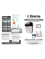
BULKLED
The fitting should light when switched on.
BULKLEDPC
The fitting will light when the power has been
restored and the ambient light level falls below the
preset threshold on the photocell (note this unit is
not adjustable).
BULKLEDMW - UNDERSTANDING THE
SETTINGS: (SEE PG 1 FOR MW DIAGRAM)
Bulkhead mounting height 2.5m
SENSITIVITY / DETECTING
Turn the screw completely anti-clockwise direction
to select minimum detection distance (approx 1m
radius), and turn sensitivity screw completely in a
clockwise direction to select the maximum detection
distance (approx 10m radius).
TIME SETTINGS
The light can be set to stay ON for any period of time
between approx 5sec (dial screw turned fully anti-
clockwise) and a maximum of 12min (dial turned fully
clockwise). Any movement detected during the “on”
time will reset the timer.
The LED indicator will flash when adjusting the time
setting dial.
The number of flashes means the following:
NOTE:
after the light switches off, it takes approx
1 sec before it is able to start detecting movement
again. The light will only switch on in response to
movement once this period has elapsed.
LUX CONTROL SETTING
Turn the Lux setting screw fully anti-clockwise to
select dusk to- dawn operation at approx 2 Lux.
Turn the Lux screw fully clockwise to select daylight
operation at approx 2000lux.
SETTING THE UP THE FITTING
Turn the Lux setting screw fully clockwise so fitting
will work in daylight, and set the time screw to
minimum setting you can then carry out the walk
test when adjusting the sensitivity/detection screw
for the required detection area, once set you can
re-adjust the Lux /time screw to the desired setting.
MICROWAVE SENSOR TECHNICAL
SPECIFICATIONS:
Power Supply
220-240Vac
Power Frequency
50/60Hz
Hf System
5.8GHz CW Radar, ISM Band
Transmission Power <10mW
Rated Load:
1200W Max.
Detection Angle
360°
Reach:
1-10m (Radii.), Adjustable
Time Setting
5 Sec to 12 Min
Light Control
2~2000LUX
Fig 1
Drill knock-out using
a 20mm hole saw
DO NOT USE A HAMMER!
BULKLED / BULKLEDMW
BULKLEDPC
L
N
Blue
(Power Cable)
Brown
(Power Cable)
Blue
(Power Cable)
Brown
(Power Cable)
L
N
Blue
(Power Cable)
Brown
(Power Cable)
Blue
(Power Cable)
Brown
(Power Cable)
DO NOT USE
PHOTOCELL
Flashes
Time
Flashes
Time
1
5 secs
6
4 mins
2
15 secs
7
6 mins
3
30 secs
8
8 mins
4
60 secs
9
10 mins
5
2 mins
10
12 mins
RED DIRECTIVE
Eterna Lighting Ltd
Microwave Occupancy Sensor
Full declaration available at www.eterna-lighting.co.uk


