


ETC Installation Guide
Heritage Contact Station
Unison
®
Heritage Contact Station Installation Guide
Page 3 of 4
ETC
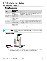
2:
Connect station ESD ground wire pigtail.
a: Strip 3/8” (9-10 mm) of insulation from the ends of the station ground wire pigtail, provided in
the termination kit, and the incoming ground wire.
b: Use one WAGO connector, provided in the termination kit, to connect the station ESD ground
pigtail and the incoming ground. For stations using grounded metal conduit, connect the ground
pigtail to the metal switch box ground location.
c: Install the ESD ground wire pigtail Faston connector to the spade terminal to the station.
3:
Terminate and connect LinkConnect wires. LinkConnect is topology free and polarity independent.
You may install LinkConnect in any combination of bus, loop, star or home-run. The total combined
length of a LinkConnect wire run (using Belden 8471, or equal) may not exceed 1,640 feet (500 m)
with a maximum distance of 1,312 feet (400 m) between any two devices.
a: Strip 3/8” (9-10mm) from the ends of each power pigtail wire, provided in the termination kit,
and the installed control wires.
b: Use the provided WAGO connectors to connect the LinkConnect power pigtail wires and the
installed Belden 8471 control wires. One WAGO should be used for the white wire pair (data +)
and one for the black wire pair (data -). Open the terminal levers on the WAGO connector and
insert the installed Belden 8471 wire and the lead from the LinkConnect power pigtail into the
terminals then close the levers.
c: Install the two pin connector from the LinkConnect power pigtail to the mating receptacle on the
station electronics.
4:
Terminate and connect Auxiliary Power (24 Vdc) wires.
a: Strip 3/8” (9-10 mm) from the ends of each auxiliary power pigtail wire, provided in the
termination kit, and the installed power wires.
b: Use the provided WAGO connectors to connect the auxiliary power pigtail wires and the installed
16 AWG (1.5 mm
2
) wires. One WAGO should be used for the red wire pair (positive) and one for
the black wire pair (negative). Open the terminal levers on the WAGO connector and insert the
installed wire and the lead from the power pigtail into the terminals then close the levers.
c: Install the two pin connector from the auxiliary power pigtail to the mating receptacle on the
station electronics.