ETC Installation Guide
SmartSwitch to Echo Relay Panel Feedthrough Retrofit Kit
SmartSwitch to Echo Relay Panel Feedthrough Retrofit Kit
Page 4 of 14
ETC
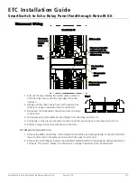
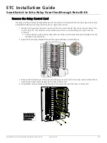
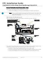
Disconnect Wiring
1. Fold out the tabs holding the ribbon cable in place in
both the relay interior and the top edge of the user
interface.
2. Gently pull the ribbon cable from both headers. This
cable is no longer needed and can be discarded.
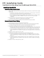
3. Disconnect the RJ45 cable connections from the relay
control card.
4. Disconnect all control cables (red and black) from the relay control card.
5. Pull gently on the orange connector to disconnect the power input to the relay control card.
6. Replace orange connectors with green connectors.
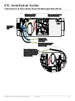
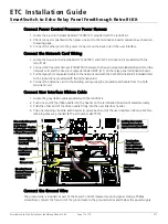
For 48-position panel only:
1. Remove the RJ45 connections, red and black control cables, and orange header connection from the
lower control card in the same manner as with the upper control card.
2. Remove the two Phillips screws securing the RJ45 splitter board to the back panel of the SmartSwitch
enclosure. The screws, bracket, and board are no longer needed and can be discarded.
Disconnect the RJ45
cables on both the
upper and lower relay
control cards.
Ribbon cable
I/O connector
panel
User interface
panel
Relay
interior
Disconnect
power in to
control
card.
Disconnect power to
control card.
SmartSwitch 48
Step 1


