


ETK-V1.1 - User’s Guide
21
ETAS
Hardware Description
The measured data stored here can be transferred to the calibration and devel-
opment system via the serial ETK interface.
4.5.3
Triggering of Measurement Data Acquisition
The exact procedure for capturing measured data is explained in the documen-
tation Display Table 13; only the hardware-specific features are mentioned here.
The ECU microcontroller initiates a data acquisition task by writing an arbitrary
value to the trigger address at the so called trigger segment. The software of the
ECU is able to start different data acquisition tasks by writing different trigger
addresses (trigger 1 to trigger 32).
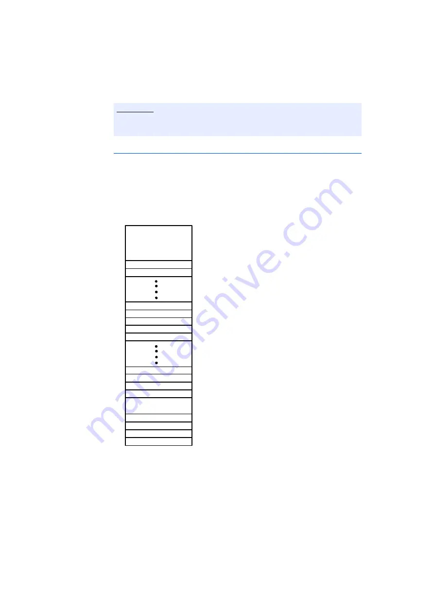
Fig. 4-9
Division of the 256 Byte Trigger Segment
The ETK-V1.1 contains a trigger comparator which can be configured to select a
segment of 256 Byte out of the measurement data memory address space (at a
256 Byte limit). This limit is known as the trigger segment address. Fig. 4-9 "Divi-
sion of the 256 Byte Trigger Segment" shows the configuration of the 256 Byte
trigger segment.
Note
Because there is no write protection of the data emulation memory possible, it
must be taken care not to override emulation data.
Trigger 16
Trigger 15
Trigger 14
00h
3Ah
3Ch
3Eh
RESERVED
Trigger 3
Trigger 4
Trigger 1
Trigger 2
24h
22h
20h
26h
08h
RESERVED
no Flash->DPR
ETK_Enable
ETK_Disable
02h
Trigger 17
40h
Trigger 18
42h
Trigger 31
5Ch
Trigger 32
5Eh
RESERVED
80h
60h


