ETAS ES4100.1 Скачать руководство пользователя страница 6

ES4100.1 Chassis VME64x - User’s Guide

6

Introduction

ETAS

1.1.3

Connecting/Removing Devices

Please take the following precautionary measures to avoid any injuries and dam-
age to hardware:

• Do not apply any voltages to the ports of the ES4100.1 Chassis VME64x 

which do not correspond to the specifications of the relevant port. Refer 
to the corresponding boards’ manuals for the exact specification of the I/
O hardware.

• Do not connect or disconnect any devices while the ES4100.1 Chassis 

VME64x or external devices are powered on. 
First, power off the ES4100.1 Chassis VME64x by using the on/off switch 
on the front of the device, and detach all power plugs.

• When inserting any connectors, please make sure they are absolutely 

straight and that none of the pins are bent.

1.1.4

Opening the Housing

The ES4100.1 Chassis VME64x must only be opened by qualified technical per-
sonnel!

1.1.5

Requirements made of the User and Obligations of the Operator

Make sure you only assemble, operate and maintain the product if you have the
relevant qualification for and experience with this product. Incorrect usage or
operation by users without an appropriate qualification can lead to serious or
even fatal injuries as well as damage to property.

General Occupational Health and Safety

The existing regulations on occupational health and safety as well as accident
prevention must be adhered to.

1.1.6

Correct Use

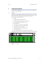
The ES4100.1 Chassis VME64x is a system housing creating a hardware-in-the-
loop test system. The ES4100.2-based hardware-in-the-loop test system consists
of:

• Digital and analog interfaces to the ECU, which can be integrated into the 

ES4100.1 Chassis VME64x as VME-based boards. 

• Battery node simulation (e.g. K15, K30, …) for connecting to the ECU 

which can be integrated into the ES4100.1 Chassis VME64x in the form of 
VME-based boards.

DANGER!

As long as the ES4100.1 Chassis VME64x is not completely discon-
nected, there is a danger of electrocution!
Disconnect the device from the mains by removing the mains cable – 
then wait a few minutes until all components (e.g. power pack, 
capacitors) are discharged.

Note

Responsibility for the safety of the system into which the ES4100.1 Chassis 
VME64x was integrated lies with the person who assembled the system!

Содержание ES4100.1

Страница 1: ...ES4100 1 Chassis VME64x User s Guide...

Страница 2: ...gle license Using and copying is only allowed in concurrence with the specifications stipulated in the contract Under no circumstances may any part of this document be copied reproduced transmitted st...

Страница 3: ...ions of the Operator 6 1 1 6 Correct Use 6 1 2 Identifications on the Product 8 1 3 CE Marking 8 1 4 RoHS Conformity 8 1 4 1 European Union 8 1 4 2 China 8 1 5 Taking the Product Back and Recycling 9...

Страница 4: ...Contents ETAS 3 2 Removal of VMEbus Boards 17 3 3 Fuses 18 4 Connections and Connectors 21 4 1 VME64x 21 4 2 Power Cables 22 5 Technical Data 23 5 1 Fulfilled Standards and Norms 25 5 2 Ordering Data...

Страница 5: ...llowing safety instructions are used They provide extremely important information Please read this information carefully 1 1 2 General Safety Information Please read the following safety instructions...

Страница 6: ...relevant qualification for and experience with this product Incorrect usage or operation by users without an appropriate qualification can lead to serious or even fatal injuries as well as damage to p...

Страница 7: ...s with conditions outside the specified ranges see Envi ronmental Conditions on page 25 Demands made of Operation The following requirements are made to ensure safe operation Only use the product in a...

Страница 8: ...oHS conformity ETAS confirms that the product corresponds to this directive which is applicable in the European Union 1 4 2 China ETAS confirms that the product meets the product specific applicable g...

Страница 9: ...ecycled in a resource saving way representing no danger to health or the environment Fig 1 1 WEEE Symbol The WEEE symbol on the product or its packaging shows that the product must not be disposed of...

Страница 10: ...the technical data of the ES4100 Chassis in tabular form and information on fulfilled standards and norms 1 6 1 Using This Manual Representation of Information All activities to be carried out by the...

Страница 11: ...lick OK Buttons are shown in boldface blue Press ENTER Keyboard commands are shown in angled brackets in block capitals The Open File dialog box appears Names of program windows dialog boxes fields et...

Страница 12: ...ES4100 1 Chassis VME64x User s Guide 12 Introduction ETAS...

Страница 13: ...has the following features 21 slots standard VMEbus and VME64x boards slots for standard eurocards 100 mm x 160 mm slots separated at 4 HP intervals 22 3 mm 160 pin backplane 3 3 V 5 V 12 V and 12 V...

Страница 14: ...2 Cut out Section of the Chassis 2 4 Display Elements The front panel of the chassis has six LEDs and a control lamp in the power switch that show you various operating and error statuses CAUTION The...

Страница 15: ...supply voltages of the ES4100 1 Chassis VME64x backplane are protected by fuses see Fuses on page 18 The regional requirements for power cords and order number are listed in Tab 4 2 on page 22 2 8 Ven...

Страница 16: ...ES4100 1 Chassis VME64x User s Guide 16 Functional Description ETAS...

Страница 17: ...top and bottom of the board smoothly slide in the guide rails Push the board in until the connector securely locks into place Fasten the mounting screws for the front panel of the board Connect the r...

Страница 18: ...t the power supply voltage there are two mains fuses on the backside of the ES4100 1 at the bottom right for specification see Tab 3 2 WARNING Failure to observe the fuse specification can lead to exc...

Страница 19: ...n six small cross head screws on the right side and six small cross head screws on the left side Mount the fuses in the respective fuse holders The fuse holders are marked according to the value of th...

Страница 20: ...ES4100 1 Chassis VME64x User s Guide 20 Operation ETAS...

Страница 21: ...svU 6 GND D05 BG1IN D13 n c 7 MMD D06 BG1OUT D14 n c 8 GND D07 BG2IN D15 RsvU 9 MCTL GND BG2OUT GND GAP 10 GND SYSCLK BG3IN SYSFAIL GA0 11 RESP GND BG3OUT BERR GA1 12 GND DS1 BR0 SysReset 3 3 V 13 Rsv...

Страница 22: ...s ETAS devices with PRC 3 and IEC 60320 C13 plug Rated for 250 VAC 10 A 2 50 m length F 04A 109 512 Europe Korea AC supply cable for Europe and Korea for var ious ETAS devices with CEE7 7 and IEC_6032...

Страница 23: ...on ETAS logo Product name Type part number Serial number Barcode for serial number Permissible input voltage range Permissible input voltage frequency Max current consumption with the corresponding in...

Страница 24: ...mm w o front handles 382 0 mm incl front handles Weight slots empty 13 5 kg 30 lbs Output voltages 3 3 V max 15 A 5 V max 12 A 12 V max 5 A 12 V max 5 A Input voltage range 100 240 VAC 50 60 Hz Connec...

Страница 25: ...lution degree 2 Permissible ambient temperature during operation 5 C to 40 C 41 F to 104 F Permissible storage temperature 20 C to 65 C 4 F to 149 F Relative humidity 0 to 95 non condensing Implementa...

Страница 26: ...ES4100 1 Chassis VME64x User s Guide 26 Technical Data ETAS...

Страница 27: ...port For details of your local sales office as well as your local technical support team and product hotlines take a look at the ETAS website Borsigstra e 24 Phone 49 711 3423 0 70469 Stuttgart Fax 49...

Страница 28: ...ES4100 1 Chassis VME64x User s Guide 28 ETAS Contact Addresses ETAS...

Страница 29: ...Documentation 5 E Electrical safety 7 ETAS Contact Addresses 27 F Features 13 Front panel 13 I Identifications on the product 8 Incorrect use 6 O Occupational health and safety 6 7 Opening the housin...

Страница 30: ...ES4100 1 Chassis VME64x User s Guide 30 Index ETAS T Technical data 23 U Use correct 6 V Ventilation fan 24 W Waste Electrical and Electronic Equip ment 9 WEEE take back system 9...

Отзывы: