ESX Vision Naviceiver VNS720 FI-DUCATO Скачать руководство пользователя страница 9

9

CONNECTION DIAGRAM / Anschlussdiagramm

            Camera connections G71-CCD0037

Name 

      Connector/Color 

Function 


CCD-CVBS-IN 

RCA yellow 

Video signal input from the rear camera

FRONT-CCD-IN 

RCA yellow 

Video signal input from the front camera

REVERSE IN 

blue 

Reverse gear signal input. Please don‘t use when vehicle‘s CANBUS is operated. 


If CAN signal is not present, the reverse signal (12V, for example the reversing  


light) can be connected here. The ESX device switches to the „CCD CVBS IN“  


input as soon as „REVERSE IN“ is supplied with 12V and „CCD-Camera“


checkbox in the option menu under „DISPLAY“ is activated.

CCD-POWER OUT 

yellow 

12V power supply output for an aftermarket rear view camera with max.  


100mA. 12V will be supplied, as soon as „REVERSE-IN“ is supplied with 12V.

FRONT CCD-POWER OUT  red 

12V power supply output for an aftermarket rear view camera with max.  


500mA. 12V will be supplied, as soon as the ESX device is turned on. 


Make sure that your camera is suitable for continuous operation.

GND 

black 

Ground terminal of the power supply of an optional camera (front and rear).

Connect the reverse signal (12V when reverse gear is engaged, for example, also by reversing light) of the vehicle to „REVERSE“ (blue 
cable). The „GND“ and „CCD POWER OUT“ cables must not be connected mandatory, but can be used as a power supply for the camera.
Now activate the „CCD-Camera“ checkbox under APPS -> OPTIONS -> DISPLAY at the ESX device.

Operation note:


- Special feature: Push the right rotary controller to display the rear view cam, even when the reverse gear is not engaged.
- When the reverse gear is engaged, the device does not allow any other operation, all the buttons and controllers except
  volume controller are blocked for security reasons. If the device is switched off and the reverse gear is engaged, the device 
  does not even turn on.

Installation note with original OEM camera for type 290 Model:

 If the CANBUS cable set „VNA-DUC-CAN-SET“ (See page 3) is used, 

only the yellow RCA plug „CCD CVBS IN“ must be connected. All other signals are taken over by the CANBUS.

FRONT VIEW CAMERA

Connect the camera via RCA to the yellow RCA connector „FRONT CCD IN“. 
Switch to „Camera“ or „Front Camera“ in the menu „AV/TV“ to display your camera view.

            Audio/Video Outputs G71-MNV0009

Name 

      Connector/Color

AUDIO L OUT/ZONE-1 

RCA white

AUDIO R OUT/ZONE-1 

RCA red

V-OUT1/ZONE-1 

RCA yellow

AUDIO L OUT/ZONE-2 

RCA white

AUDIO R OUT/ZONE-2 

RCA red

V-OUT2/ZONE-2 

RCA yellow

IMPORTANT NOTE: 

Connection for e.g. headrest monitors or other devices such like TVs in the rear. The audio/video outputs is always 

the same signal to which will be played just on the ESX device. An independent input source selection is not possible.

9

10

Содержание Vision Naviceiver VNS720 FI-DUCATO

Страница 1: ...E IN B A U A N L E IT U N G IN S T A L L A T IO N G U ID E V 1 1 VNS720 FI DUCATO...

Страница 2: ...es Soundsystems und die Komponenten Ihres Fahrzeugs grunds tzlich mit Vorsicht 2 Beachten Sie unter allen Umst nden die Vorschriften des Fahrzeugherstellers und nehmen Sie keine Ver nderungen am Fahrz...

Страница 3: ...a auf ISO 50 Ohm USB Adapter USB A auf Mini USB B Kupplung Unterst tzt originale R ckfahrkamera Scope of delivery 4 Lieferumfang 4 Connection Diagram 6 Anschlussdiagramm 6 Installation notes 12 Instal...

Страница 4: ...1 5 G71 AUD0119 AUDIO VIDEO AV INPUTS Audio Video AV Eing nge 1 6 G71 MNV0010 AUDIO OUTPUTS 5 1 WITH REMOTE TURN ON Audio Ausg nge 5 1 mit Einschaltleitung 1 7 G71 WHE0063 VAR SYSTEM CONNECTIONS E G...

Страница 5: ...ITH QUICK CHARGE FUNCTION USB Anschluss 1 2 mit Schnellldadefunktion 2 12 GPS ANTENNA GPS Antenne 1 14 Y ANTENNA ADAPTOR WITH 2 5 MM INPUT JACK UNIVERSAL ISO CONNECTOR Y Antennen Adapter mit 2 5 mm Kl...

Страница 6: ...NTENNA AM FM Antenne FUSE Ger tesicherung CONNECTION DIAGRAM Anschlussdiagramm EXTERNAL BT MICROPHONE Externes BT Mikrofon VAR SYSTEM CONNECTIONS E G DAB BOX Div System Anschl sse z B DAB Box AUDIO VI...

Страница 7: ...PEAKER FRONT LEFT SPEAKER FRONT LEFT SPEAKER REAR LEFT SPEAKER REAR LEFT KEY1 KEY2 AUX GROUND AUX SIGNAL R AUX SIGNAL L CAN LOW CAN HIGH Dauerplus Antenne Beleuchtung Z ndungsplus Masse Lautsprecher h...

Страница 8: ...D plack Ground wire to 12V OUT TV CONT OUT brown Control cable for special ESX devices please do not use BRAKE IN pink Connect to the parking brake signal to the device The cable provides ground when...

Страница 9: ...es must not be connected mandatory but can be used as a power supply for the camera Now activate the CCD Camera checkbox under APPS OPTIONS DISPLAY at the ESX device Operation note Special feature Pus...

Страница 10: ...le Stromaufnahme 500 mA GND schwarz Masseleitung zu 12V OUT TV CONT OUT braun Steuerleitung f r spez ESX Ger te Bitte nicht verwenden BRAKE IN rosa Schlie en Sie hier das Handbremssignal an das Ger t...

Страница 11: ...s Stromversorgung f r die Kamera verwendet werden Aktivieren sie abschlie end den Punkt CCD Kamera unter APPS OPTIONEN Bildschirm Bedienhinweis Als besondere Funktion kann die R ckfahrkamera bei diese...

Страница 12: ...desired mounting point at the A pillar driver s side while laying the cable over the the passenger s side A possibly existing factory microphone is not compatible with the ESX device BT Mikrofon Das G...

Страница 13: ...turned of while driving The video outputs 10 are not affected Note If you have connected the CANBUS the brake signal must not be con nected Handbremsen Anschluss Das Handbremssignal muss an das beilie...

Страница 14: ...n Fiat Ducato III Modell von Dethleffs Aufgrund der vielen verschiedenen Ausstattungs varianten der Fiat Ducato Plattform k nnten einige Beschreibungen und Installa tionshinweise in dieser Einbauanlei...

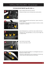
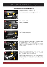
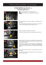
Страница 15: ...zu installieren Remove the lower glove box Loosen the three screws as marked on the image Entfernen Sie das untere Handschuhfach L sen Sie die drei Schrauben wie auf dem Bild markiert Loosen the fourt...

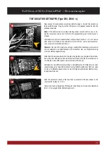
Страница 16: ...die im Lieferumfang enthaltene ESX Einbauhalterung im Radio schacht Verwenden Sie daf r die beiliegenden Schrauben Verlegen Sie nun die Anschlusskabel des neuen ESX Ger ts Siehe S 4 5 im Fahrzeug vom...

Страница 17: ...ion das Zubeh rkabel 15 Beachten Sie zur Programmierung S 40 der Bedienungsanleitung Slide the ESX device carefully into the radio bay Before you complete the installa tion of the new ESX device check...

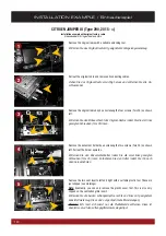
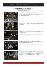
Страница 18: ...holder upwards Entfernen Sie den Dokumentenhalter indem Sie die zwei links gezeigten Schrauben Torx 25 l sen Entnehmen Sie den Halter indem Sie ihn nach oben herausnehmen Remove the two vent inserts...

Страница 19: ...ove the cover of the hazard switch cigarette lighter including cup holders unit from below with a suitable plastic tool Then remove all cables on the back and put the panel aside Entfernen Sie die Ver...

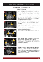
Страница 20: ...blende Diese ist nur noch ganz oben an zwei Punkten geclipst From here the installation of ESX device starts Start from here if your car is equipped with the factory radio preparation Ab hier beginnt...

Страница 21: ...abel f r z B externes Mikrofon USB GPS zum gew nschten Einbauort Zudem k nnen nun auch weitere Verkabelungen wie z B f r die R ckfahrkamera zum Radioschacht verlegt werden Ber ck sichtigen Sie zudem d...

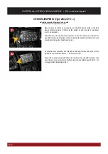
Страница 22: ...den Radioschacht und f hren Sie eine Funktionspr fung aller Funktionen durch If all functions are ensured push in the ESX device until it stops and clicks in Then perform the re assembly Step 5 14 in...

Страница 23: ...adapter 15 Schlie en Sie hierf r folgenden Adapter 15 an Remove the cover of the fuse box 2 x Phillips PH2 Entfernen Sie die Abdeckung des Sicherungskastens 2 x Kreutzschlitz PH2 First refer to the in...

Страница 24: ...cables containing the CAN BUS Take before connecting the ESX device the adapter 15 at hand and lay the two long cable ends CANH and CANL from the radio bay to the fuse box WARNING Make sure that the c...

Страница 25: ...25 NOTES Notizen...

Страница 26: ...26 NOTES Notizen...

Страница 27: ...27 NOTES Notizen...

Страница 28: ...D E S I G N ESX Car Media Systems Audio Design GmbH Am Breilingsweg 3 D 76709 Kronau Germany Tel 49 7253 9465 0 Fax 49 7253 946510 www esxnavi de www audiodesign de 2017 All Rights Reserved...

Отзывы: