


9
Wiring the outputs
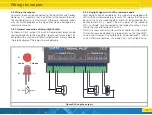
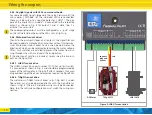
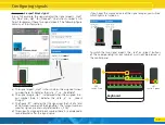
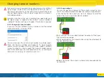
5.4. Wiring the outputs
Consumer loads can be connected to the SignalPilot very flexibly.
However, it is important that in addition to the correct terminal,
the configuration must also match. Otherwise, consumer loads
may not switch properly or the SignalPilot may be damaged in a
worst-case scenario.
5.4.1. General connection of lamps (light bulbs)
As shown in Fig. 4, outputs 15 and 16, incandescent lamps can be
connected directly to the SignalPilot. Ideally, use lamps rated 16V
or higher with a maximum of 50mA rated current. Always observe
the rated voltage of the lamps to avoid damage.
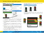
5.4.2. Daylight signals with LEDs, common anode
Most daylight signals available on the market are equipped with
LEDs with common anode (e.g.: Busch). This means that the ano-
des of all LEDs are wired together and must be connected to a
positive potential („+” pole). The minus poles of the individual
LEDs („cathode”) are connected to the respective output. Fig. 4
shows the wiring for outputs 9 and 10.
If LEDs are used, a series resistor must be used to limit the current.
The resistance value depends to a large extent on the type of LED,
so no exact statement is possible here. Values between 1 kOhm
and 10 kOhm are common. If in doubt, start with a higher value.
Figure 4: Wiring the outputs
R
+ -
Anode
Cathode
+ -
+ -
R


