5.8.
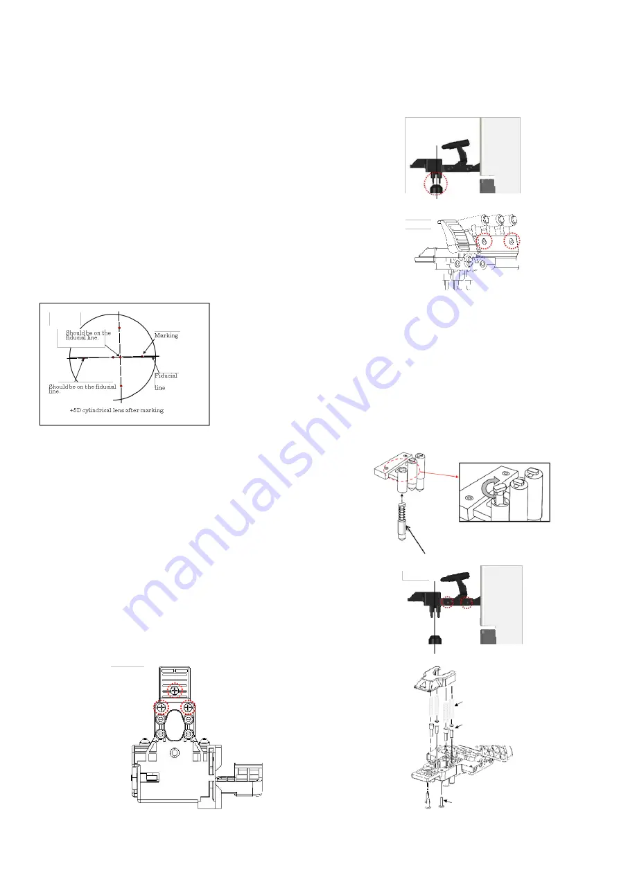
Marking pen, retention pin, marking / Retention unit assy.
1)
Replacement of marking/ retention unit Assy.
-
Removal
Unscrew 2 screws (cross recessed binding screw M3×10 black) fixing the marking/ retention unit Assy.
-
Installation
Install the marking/retention unit Assy. so that the lens
retention pin is positioned roughly in the center of the light
receiving unit.: Fig. 4
Check the marking position by taking a measurement of
cylinder lens of the maintenance lens set.
[Fig.4]
Adjustment when marking is not on fiducial line
Loosen 2 screws (hexagonal socket cap bolt M2×6 black)
fixing the marking unit, adjust it so as that the marking is
on the cylindrical lens in the maintenance lens set and fix
the marking unit. :Fig. 5
[Fig.5]
<Confirmation procedure>
Perform alignment by placing +5D cylindrical
lens with contacting with the lens plate in the
direction of AX 180. At this time, adjust the
marking unit so as that the marking is on the
fiducial line.
Then, perform alignment by placing +5D
cylindrical lens with contacting
with the lens plate in the direction of AX 90
without erasing the marking. At this time, the
marking in the middle should be on the fiducial
line.
2)
Replacement of Marking Pen
Press the marking pen as shown below and rotate it 90
degrees. Insert the new pen in the original position.
3)
Replacement of Lens Retention Pin
Unscrew 2 screws (cross-recessed bind screw M3×10
black) fixing the marking/ retention unit Assy. :Fig. 1
Unscrew 3 screws (cross-recessed bind head tapping
screw 2×8 black) fixing the lens retention unit. Replace
the pins by disassembling the lens retention unit. :Fig. 2
and 3
[Fig.1]
[Fig.2]
[Fig.3]
Marking pen
Cross recessed bind head
tapping screw 2x8 black
Lens retention pin
Compression spring
Содержание ALM 700
Страница 1: ...Maintenance manual Auto Lensmeter ALM700 V1 10 2016...
Страница 36: ......


