Art. No. 11142
All rights reserved. Reproduction as well as electronic duplication of this user guide, complete or in part, requires the written consent of
ESERA GmbH. Errors and technical modification subject to change.
ESERA GmbH, ESERA-Automation 2020
www.esera.de
11142 V2.0 R1.0 Manual
Page 3 of 4
6
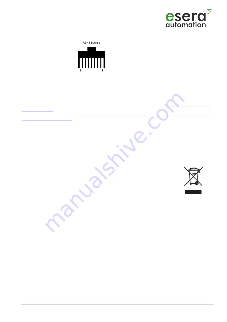
Assignment RJ45 socket
1
GND
2
+5VDC
3
GND
4
1-Wire Data
5
GND
6
unoccupied
7
+12VDC
8
GND
7
Push-In socket (input/output)
The Push In terminal and the RJ45 socket are connected in parallel, which means that both connections can be
used equally.
8
1-Wire Network
Basics and tips for the 1-Wire bus system can be found in the ESERA Online Shop at
or please refer to our eBook, available for purchase in the shop under
Training/Documentation (
https://www.esera.de/service-support/dokumentation/352/grundlagen-1-wire-
9
Operating conditions
The device may only be used in dry indoor areas. The module can be operated in any position.
The device is designed for mounting on top-hat rails, such as those used in fuse cabinets.
10
Assembly
The installation site must be protected from moisture. The device may only be used in dry indoor rooms and in
protected outdoor areas.
The device is intended for installation inside a control cabinet as a stationary device.
11
Disposal note
Do not dispose of the device within the household waste!
According to the directive concerning old electrical and electronic appliances,
electronic devices must be disposed of via the collecting points for old electronic
appliances!
12
Safety instructions
When using products that come into contact with electrical voltage, the valid VDE regulations must be observed, especially
VDE 0100, VDE 0550/0551, VDE 0700, VDE 0711 and VDE 0860
All final or wiring work must be carried out with the power turned off.
Before opening the device, always unplug or make sure that the unit is disconnected from the mains.
Components, modules or devices may only be put into service if they are mounted in a contact proof housing.
During installation they must not have power applied.
Tools may only be used on devices, components or assemblies when it is certain that the devices are disconnected
from the power supply and electrical charges stored in the components inside the device have been discharged.
Live cables or wires to which the device or an assembly is connected, must always be tested for insulation faults or
breaks.
If an error is detected in the supply line, the device must be immediately taken out of operation until the faulty cable
has been replaced.
When using components or modules it is absolutely necessary to comply with the requirements set out in the
accompanying description specifications for electrical quantities.
If the available description is not clear to the non-commercial end-user what the applicable electrical characteristics
for a part or assembly are, how to connect an external circuit, which external components or additional devices can
be connected or which values these external components may have, a qualified electrician must be consulted.
It must be examined generally before the commissioning of a device, whether this device or module is basically
suitable for the application in which it is to be used.
In case of doubt, consultation with experts or the manufacturer of the components used is absolutely necessary.
For operational and connection errors outside of our control, we assume no liability of any kind for any resulting
damage.


