


Overview
1. Overview
1.1 Module Description
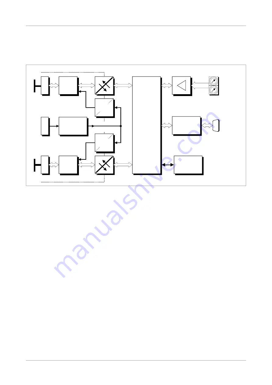
Figure 1:
Block circuit diagram of CAN-CBM-Bridge/2
The module CAN-CBM-Bridge/2 can connect two independent CAN nets. The nets can be
operated with different bit rates.
The module works with a MB90F453 microcontroller which buffers CAN data into a local SRAM.
The firmware is contained in the flash. Parameters are stored in a serial EEPROM.
The ISO 11898-compliant CAN interfaces allow a maximum data transfer rate of 1 Mbit/s each.
The CAN interfaces are electrically isolated by optical couplers and DC/DC converters. They are
connected via 5-pin screw/plug connectors.
For matters of service and development the module features a serial interface. RS-232 is used as
physical interface. It is connected via a DSUB9 connector.
CAN-CBM-Bridge/2
Hardware Manual • Doc. No.: C.2853.21 / Rev. 1.4
Page 9 of 41
+5 V=
+5 V=
C
A
N
B
U
S
CAN
Physical
CAN
Layer
+5 V=
+5 V=
DC/DC-
Wandler
C
A
N
B
U
S
Physical
CAN
Layer
MSTB2,5/5-5,08
CAN
Microcontroller
MB90F543
electrical isolation
DC/DC
Converter
MSTB2,5/5-5,08
DSUB9
Connector
3-pole UEGM
Connector
Serial
EEPROM
Coding Switches
Serial Interface
RS-232
Power Supply
24 V(DC)
electrical isolation