Declaration of Conformity
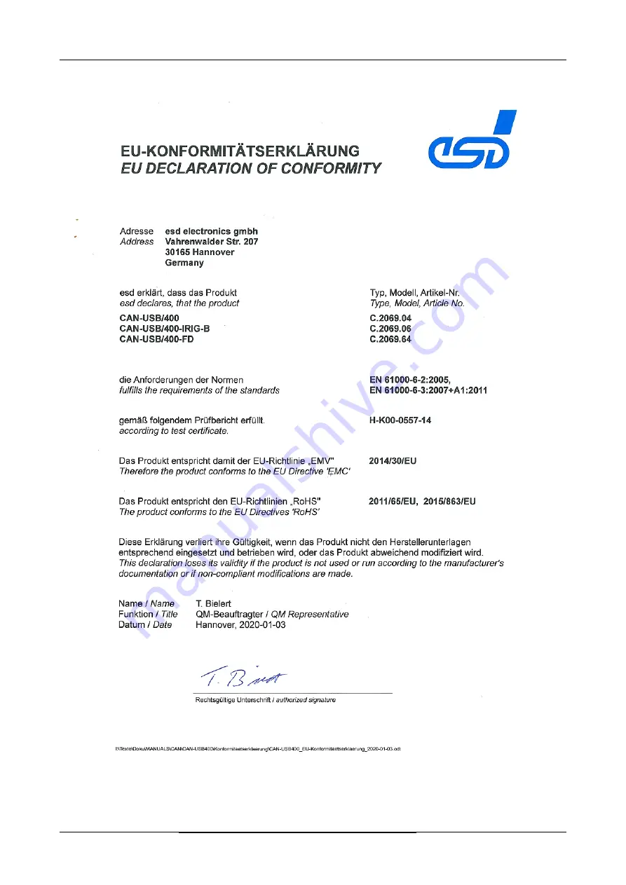
8. Declaration of Conformity
Page 32 of 34
Hardware Manual • Doc. No.: C.2069.21 / Rev. 1.4
CAN-USB/400 / -IRIG-B / -FD
Страница 1: ...ional IRIG B Input or 2x CAN FD Hardware Manual to Products C 2069 04 C 2069 06 C 2069 64 CAN USB 400 IRIG B FD Hardware Manual Doc No C 2069 21 Rev 1 4 Page 1 of 34 esd electronics gmbh Vahrenwalder...
Страница 2: ...approval 2020 esd electronics gmbh Hannover esd electronics gmbh Vahrenwalder Str 207 30165 Hannover Germany Phone 49 511 372 98 0 Fax 49 511 372 98 68 E Mail info esd eu Internet www esd eu This man...
Страница 3: ...Notes concerning EMC conformity inserted 5 3 Connector is only equipped on CAN USB 400 IRIG B wiring guidelines inserted 6 7 Chapters updated 8 New Chapter Declaration of Conformity 9 Chapter moved 1...
Страница 4: ...s indicate a hazardous situation which if not avoided will result in death or serious injury WARNING Warning statements indicate a hazardous situation that if not avoided could result in death or seri...
Страница 5: ...pecified in the technical data Qualified Personnel The installation and commissioning of the product may only be carried out by qualified personnel which is authorized to put devices systems and elect...
Страница 6: ...5 1 USB 18 5 2 CAN0 CAN1 19 5 3 IRIG B Trigger and I Os CAN USB 400 IRIG B only 20 6 Correct Wiring of Electrically Isolated CAN Networks 22 6 1 Standards concerning CAN Wiring 22 6 2 Light Industrial...
Страница 7: ...by esd 31 8 Declaration of Conformity 32 9 Order Information 33 9 1 Software for CAN USB 400 and CAN USB 400 IRIG B 33 9 2 Software for CAN USB 400 FD 34 9 3 PDF Manuals 34 CAN USB 400 IRIG B FD Hard...
Страница 8: ...driven by the ISO 16845 2004 certified esdACC esd Advanced CAN Core implemented in the Altera FPGA Attached to USB via FIFO s and driven by the esdACC the CAN USB 400 is designed for minimum latency C...
Страница 9: ...ds compatible with CAN As customized option the analog and digital IRIG B inputs are available on request Customized options are available for customized series production in reasonable quantities Ple...
Страница 10: ...ED and Connector Description Figure 4 CAN connectors and LEDs CAN USB 400 IRIG B view Figure 5 USB and IRIG B CAN USB 400 IRIG B view See page 18 for signal assignment of the connectors Page 10 of 34...
Страница 11: ...er has not yet been loaded Both LEDs are blinking in alternating sequence CAN1 CAN0 on Driver loaded Driver loaded and no traffic on CAN0 or CAN1 CAN1 CAN Traffic This indicator state is indicated ind...
Страница 12: ...e EC Conformity shielded cables have to be used In an adapter cable FE functional earth shall be connected to the cable shield 2 Please note that the CAN bus has to be terminated at both ends esd offe...
Страница 13: ...m x 86 mm Weight 145 g Table 2 General data of the module INFORMATION Please note that the current consumption of the module has to be supplied high powered bus powered device The maximum current cons...
Страница 14: ...or DSUB9 according to DS 303 1 Table 5 Data of the CAN interface on CAN USB 400 IRIG B 4 5 CAN FD Interfaces on CAN USB 400 FD INFORMATION The CAN FD interfaces are only available on CAN USB 400 FD C...
Страница 15: ...ot examined with regard to the electromagnetic compliance and immunity This interface is for custom built evaluation kits destined for professionals to be used solely at research and development facil...
Страница 16: ...uded in the scope of delivery Multiple higher level protocols are available for Windows CANopen Master and Slave Stack J1939 ARINC825 Drivers and software support for other operating systems are avail...
Страница 17: ...ot Graphical display of CAN data CANrepro Replay of pre recorded CAN messages CANscript Python based scripting tool COBview Analysis and diagnostics of CANopen nodes System Requirements Windows 32 bit...
Страница 18: ...BUS 2 D 3 D 4 GND Signal Description VBUS 5 V power supply voltage D D USB signal lines Data Data GND Reference potential connector housing connector housings of CAN0 CAN1 USB and if applicable IRIG B...
Страница 19: ...4 reserved reserved 9 5 Signal Description CAN_L CAN_H CAN signal lines CAN_GND reference potential of the local CAN physical layer reserved reserved for future applications do not connect not connect...
Страница 20: ...odules GND signal reference GND IRIG B_RX digital IRIG B input acc to standard 200 87 format B003 IRIG B_A analog IRIG B input acc to standard 200 87 format B122 connector housing connector housings o...
Страница 21: ...Connector Assignments Wiring of the analog and the digital IRIG B interface at DSUB15 Figure 6 IRIG B wiring guidelines CAN USB 400 IRIG B FD Hardware Manual Doc No C 2069 21 Rev 1 4 Page 21 of 34...
Страница 22: ...ginal ISO 11898 They have made system level tradeoffs for data rate cable length and parasitic loading of the bus However for CAN network design margin must be given for signal loss across the complet...
Страница 23: ...D has to be connected to the functional earth FE at exactly one point 4 A CAN net must not branch exception short cable stubs and has to be terminated with the characteristic impedance of the line gen...
Страница 24: ...d at the CAN interface at the end of the bus is connected this one has to be used for termination instead of an external CAN termination plug 9 pin DSUB termination connectors with integrated terminat...
Страница 25: ...as to be terminated with the characteristic impedance of the line generally 120 10 at both ends between the signals CAN_L and CAN_H and not to CAN_GND 5 Keep cable stubs as short as possible l 0 3 m 6...
Страница 26: ...tor can be used in which the shield potential is looped through e g the DSUB9 connector from ERNI ERBIC CAN BUS MAX order no 154039 If a mixed application of single twisted and double twisted cables i...
Страница 27: ...on depending on the cable length are described in the CiA recommendation CiA 303 1 see CiA 303 CANopen Recommendation Part 1 Cabling and connector pin assignment Version 1 8 0 Table 2 Bit Rate kbit s...
Страница 28: ...ww concab de e g BUS PVC C 1x 2x 0 22 mm Order No 93 022 016 UL appr BUS Schleppflex PUR C 1x 2x 0 25 mm Order No 94 025 016 UL appr 6 6 2 Cable for heavy industrial Environment Applications Four Wire...
Страница 29: ...stance of the CAN data pair conductors and the attached terminating resistors To test it please 1 Turn off all power supplies of the attached CAN nodes 2 Measure the DC resistance between CAN_H and CA...
Страница 30: ...f there is a short circuit between CAN_GND and CAN_L but generally the error rate will increase strongly Make sure that there is no short circuit between CAN_GND and CAN_L 7 4 CAN_H CAN_L Voltage Each...
Страница 31: ...e figure below 2 Measure the DC resistance between CAN_H and CAN_GND see figure below 3 Measure the DC resistance between CAN_L and CAN_GND see figure below The measured resistance has to be about 500...
Страница 32: ...Declaration of Conformity 8 Declaration of Conformity Page 32 of 34 Hardware Manual Doc No C 2069 21 Rev 1 4 CAN USB 400 IRIG B FD...
Страница 33: ...USB 400 and CAN USB 400 IRIG B Type Order No CAN layer 2 software drivers for Windows on CD ROM to CAN USB 400 C 2069 04 and CAN USB 400 IRIG B C 2069 06 are included in delivery Higher Layer Protoco...
Страница 34: ...0 FD 9 3 PDF Manuals For availability of English manuals see table below Please download the manuals as PDF documents from our esd website www esd eu for free Manuals Order No CAN USB 400 ME Hardware...