


LEDs
Page 12 of 31
Hardware Manual Doc.-Nr.: C.2035.21 / Rev. 2.2
CPCI-CAN/200
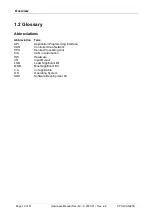
3 LEDs
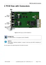
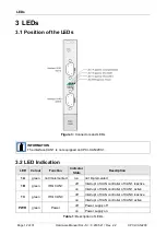
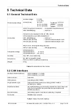
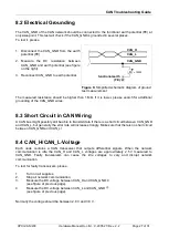
Figure 3:
Connectors and LEDs
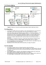
INFORMATION
The interface CAN1 is not equipped on CPCI-CAN/200-1.
LED
Colour
Function
Indicator
State
Description
1A
green
not implemented
n.a.
not implemented
1B
green
IRQ CAN 1
off
Interrupt of CAN controller of CAN1 inactive
on
Interrupt of CAN controller of CAN1 active
1C
green
IRQ CAN 0
off
Interrupt of CAN controller of CAN0 inactive
on
Interrupt of CAN controller of CAN0 active
PWR
green
Power
off
Power supply off
on
Power supply on
Table 1:
Description of LEDs
3.1 Position of the LEDs
3.2 LED Indication


