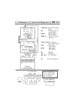
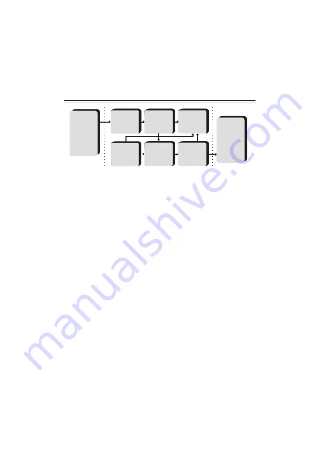
ESD 92 Series Скачать руководство пользователя страница 4

1. Transducer :

 This block consists of either a Thermocouple, Pt- 100 (RTD) or 

a 4 - 20 mA current signal. It senses the temperature and sends a signal to the 
sensor compensation circuit.

2. Signal conditioner :

 consists of a bridge generating mV signal corresponding 

to the ambient temperature. In case of thermocouple input this is added to input 
mV signal for automatic ambient temperature compensation. In case of Pt-100 
input, it gives constant current for Pt-100 excitation and provides 3 wire system 
for lead wire compensation.

3. Amplifier :

 reads the signal from the sensor and calculates the temperature. It 

consists of a bridge and an amplifier. The signal from the sensor causes an 
unbalance in the bridge. This unbalance is proportional to the temperature being 
measured. The output of the bridge is amplified and calibrated suitably. The 
amplifier o/p is fed to the display circuit and the comparator.

4. ADC & Display : 

consists of an analog to digital convertor (ADC), a digital 

voltmeter and 4 seven segment LED displays. The ADC converts the analog 
output of the amplifier to a digital signal which is read by the digital voltmeter 
and displayed on the seven segment displays, directly in terms of process 
parameter.

5. Setpoints : 

consists of ten turn highly stable potentiometer excited by 

precision regulated power supply for setting desired set values.

6. Comparator :

 compares the output of the amplifier (process value), with the 

set point set by the user. Depending on whether the process value is greater than 
or less than the set point the comparator output   is either -ve or +ve.   For ‘n’ set 
points we have ‘n’ comparators.

7. Relay :

 The relay switches ON or OFF depending on comparator output. For 

‘n’ set points we have ‘n’ relays. 

5. Block Diagram

Signal

Conditioner

Amplifier

ADC & 
Display

Comparator-1
Comparator-2

Relay -1 
Relay -2 

Setpoint -1
Setpoint -2

Field

Field

Control

 through

Contactors

Transducer

&

Transmitter

Содержание 92 Series

Страница 1: ...ctly in digits giving better resolution compared to analog indicators The ESD 92 series accepts all types of Thermocouples Pt 100 0 to 20 mA 4 20 mAas well as 0 2 5 10VDC as input Wide rangesofmeasurementsare available The instrument is immune to mechanical vibrations Even the mounting position will not affect the measurement accuracy The large bright red LED seven segment display allows long dist...

Страница 2: ...compares the process value with the desired value Set point Output of the comparator is given to the relay which switches ON or OFF depending upon the process value as compared to thesetpoint Linearisation of the input signal from the transducer is done by hardware in the input circuit This gives a standardized signal to the analog to digital convertor which drives the LED display indicating the t...

Страница 3: ...ange over contact 5 Amp resistive at 230 V AC per setpoint Relay logic 1 Actual temp set point Relay ON for Heating application Factory set 2 Actual temp set point Relay ON for Cooling application On demand Relay ON indication By Red LED per setpoint Control Sensitivity 0 25 of FS Display 3 1 2 digit 7 segment 12 5 mm Red LED Power supply 230 V AC 10 50 Hz o Ambient Temp range 0 to 55 C o Amb Temp...

Страница 4: ...r o p is fed to the display circuit and the comparator 4 ADC Display consists of an analog to digital convertor ADC a digital voltmeter and 4 seven segment LED displays The ADC converts the analog output of the amplifier to a digital signal which is read by the digital voltmeter and displayed on the seven segment displays directly in terms of process parameter 5 Setpoints consists of ten turn high...

Страница 5: ...ormer ESD 189 Relay Sensor Primary Backcard ESD 9123BK R3 E N P NC P NO R G B Relay1 Mother board ESD 9213MB4 TB User Terminals 1 2 3 4 5 6 7 8 9 CONTROL Red LED s for Relay Status SET Potentiomenters for setpoint adjust PRESS Press Switches to read set values DISPLAY 12 5 mm 7 segment RED LED VSEN Sensitivity adjust Potentiometers SPAN Span adjust Potentiometer ZERO Zero adjust Potentiometer IC1 ...

Страница 6: ...er IC1 Amplifier IC2 Comparator RL1 RL 2 12 V DC Relays Pt 100 3 WIRE RTD TC THERMOCOUPLE E N P NC P NO NC P NO C C R R C1 C2 1 2 3 4 5 6 7 8 9 SUPPLY VOLTAGE 10 11 12 Pt 100 TC Relay 1 Relay 2 2i i Display board ESD 9223DPM R1 CONTROL SET PRESS DISPLAY 10 Pin connector Secondary Sensitivity Span Zero Transformer ESD 189 Relay2 Relay Sensor Primary Backcard ESD 9223BK R2 E N P NC P NO R G B Relay1...

Страница 7: ...ion 5 Use correct compensating cables for thermocouple type instruments 6 Ensure proper earthing to the instrument 7 Output loads connected through the relay change over contact should be less than the maximum specified value 8 Connect a series combination of 0 1 F 600Vnon polar capacitor 220 1 2Wresistor across phase neutral 9 For setting set values as per your requirement press the push button a...

Страница 8: ... at 20 of Full Scale FS for ZERO calibration and at 80 of FS for SPAN o calibration i e If the range is 0 to 1000 C the ZERO calibration o should be done at 200 C 20 of FS and SPAN calibration should be o done at 800 C 80 of FS Depending on the type of input proceed as follows 8 1 Thermocoupleinput 1 Remove the thermocouple from its terminals and connect a stable mVsource in its place with proper ...

Страница 9: ... wire system in its place 2 Feed resistance corresponding to 20 value of FS eg resistance o o corresponding to 20 C for 0 to 100 C range The display should show corresponding temperature If the displayed temperature is incorrect turn the potentiometer marked ZERO to display correct reading CWto increase and CCWto decrease 3 Feed resistance corresponding to 80 value of FS eg resistance o o correspo...

Страница 10: ...36 113 99 1 85 1 47 0 21 0 21 38 114 77 2 00 1 53 0 22 0 22 40 115 54 2 06 1 61 0 30 0 24 50 119 40 2 59 2 02 0 36 0 30 60 123 24 3 12 2 44 0 43 0 37 80 130 89 4 19 3 27 0 57 0 50 100 138 50 5 27 4 10 0 72 0 65 120 146 06 6 36 4 92 0 88 0 80 140 153 58 7 46 5 73 1 04 0 95 160 161 04 8 56 6 54 1 21 1 11 180 168 46 9 67 7 34 1 38 1 27 200 175 84 10 78 8 14 1 56 1 44 250 194 07 13 55 10 15 2 02 1 87 ...

Страница 11: ...e not within specified limit Excessive Abmbient temperature Error in Indication Improper Sensor Location Improper Sensor type Calibration error Excessive Abmbient temperature Commonly observed problems and their likely causes Please read Installation Procedure and Instrumentation health prior to this In case the problem persists please refer the service manual of the product or get in touch with o...

Страница 12: ...y Certificate iv Test Certificate v Small size screw driver for setpoint adjustment In case of any discrepancies contact our customer support department immediately We are sure you will get long and troublefree service from our instrument Every attempt is made to make this Manual clear and easy to understand We believe that you will feel confident to install use and maintain our product ESD welcom...

Страница 13: ..._____________________ __________________________________ ModelNo ESD9213 ESD9223 Serial No ____________ Date _______ Warranty Certificate E L E C T R O N I C S SYSTEMS A N D DE V I C E S PUNE 13 1 The warranty is limited to repairing the instrument and no responsibility is taken for any other damage resulted 2 The warranty will be void if the instrument is tampered with in any way 3 The faulty ins...

Страница 14: ...g Information Ordering eg ESD 9213 1011 Digital Temp Controller ESD 92 No of setpoints One 1 Panel cutout 92 x 92 mm 3 Input Pt 100 1 o o Range 50 C to 50 C 0 Relay Output 1 C O 5 Amp 1 Power Supply 230 V AC 1 0 200 800 1600 Input 0 to 100 or process value mA mV Standard Ranges in o C K R S 0 400 0 600 0 800 0 1000 0 1200 J Pt 100 50 50 0 100 0 200 0 200 0 400 0 600 1 230 V AC 2 110 V AC 3 48 V AC...

Страница 15: ...onnections to the terminations and also while adjusting calibration and set points Fuses of correct ratings for mains Do s Sensor cables must be isolated from power cables Insert minimum required sensitive length in the measurement object Operating temperature should be 80 of the maximum specified temperature Check that all the wiring is firm and as per wiring diagram Loads connected should be wit...

Страница 16: ...oint value over long periods due to factors like ambient temperature time linevoltageetc Error The difference between the correct or desired value and the actual value or the value being measured Explosion proof enclosure An enclosure that can withstand an explosion of gases within it and prevent the explosion of gases surrounding it due to sparks flashes or the explosion of the container itself a...

Отзывы: