background image

7

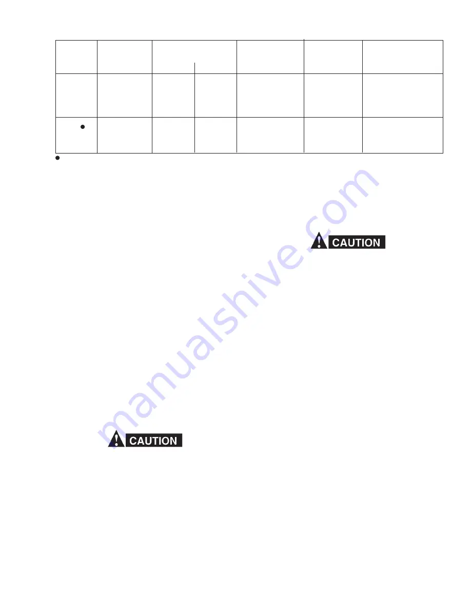
Table 3 - ST-16 Wire Feed Accessories Using Conduit/Replaceable Liner System

Wire
Type/
Size

Hard

Cored

Contact
Tube
(Slip-in)

996104
996105
996816
996106

996105
996816
996816

Contact Tip
(Threaded)

632794
632796
948335
632798

    -
    -
    -

632793
632795
948308
632797

632795
948308
632797

Long         Short

Wire Outlet Guide

29N13
29N13
29N13
29N13

29N13
29N13
29N13

Mig-35
Digimig

Replaceable

Spring

Liner

636843
598786
598786
598786

598786
598786
598786

Soft-Lined
Conduit
10-ft.. x (I.D.)

598922 (.195)
598922 (.195)
598922 (.195)
598922 (.195)

598922 (.195)
598922 (.195)
598922 (.195)

Use No. 12M Nozzle (P/N 997310).

B. USING CONDUITS WITH REPLACEABLE LIN-
    ERS

1.

Insert the torch end of the conduit through the rear
of the torch handle and into the conduit connection
fitting.
Refering to Figure 3, loosen the two No. 10-32 screws
on locking nut (598787), slide handle back, and then
lock the conduit in place by tightening the No. 10-32
setscrew on the conduit connection fitting.  Reas-
semble handle to locking nut and tighten setscrews.

2.

Insert the liner into the conduit and through the torch.
The shoulder spring about the liner should rest in-
side and below the threads of the wire feeder end of
the conduit.

3.

Slip the wire outlet guide (see Table 3) over the liner
protruding from the conduit and screw into the con-

4.

duit connection.  If necessary, adjust shoulder spring
on liner so that the end of the liner is about flush with
the end of the wire outlet guide.
Complete the installation by following steps 5 through
8 as described on page 5 , (Section IV, Using Self-
Lined Conduits).

5.

V. ADJUSTMENT & OPERATION

Before adjustments are made, disengage the pessure
roll to prevent wire from feeding and arcing to an
accidental ground.

To set the shielding gas flow rate, press the torch lever
to open the gas solenoid valve and adjust the flowmeter
to the desired flow rate.  For proper operation a minimun
flow of .40 gpm of cooling water at 60-deg.F or less,
must be maintained if the torch is to perform at rated
capacity.  A torch inlet water pressure of 25 psi minimum
will provide adequate flow.  Check these water flow re-
quirements before starting.  The wire feed conduit should
be kept as straight as possible and without sharp bends
to assure smoother wire feed.

Specific operation of the torch depends on the particular
wire feeder with which it is used.  Therefore, consult the
instruction manual supplied with the wire feeder.

VI. MAINTENANCE

If this equipment does not operate properly, stop
work immediately and investigate the cause of the
malfunction.  Maintenance work must be performed
by an experienced person, and electrical work by a
trained electrician.  Do not permit untrained persons
to inspect, clean, or repair this equipment.  Use only
recommended replacements.

A. POWER CABLE

If the power cable assembly becomes damaged, it is
recommended that (1) a new one be purchased, or (2)
the damaged unit be turned over to an ESAB authorized
repair station for repair.  The connection fittings are
crimped on at the factory by special crimping tools to
ensure strong connections and prevent leakage.  A sat-
isfactory job cannot be done without these tools.

B. GAS AND WATER HOSE ASSEMBLIES
     (Refer to Fig. 3)

If shielding gas (46V63) or water hose assemblies
(46V25) require replacement, loosen the two No. 10-32
x 3/16-in. set screws on the handle locking nut and pull
handle back.

To replace gas hose assembly, proceed as follows:

Clip off wire hose clamp (53N46) and remove hose.

1.

Clean off fitting, and then brush on some Loctite
Prism 447 (P/N 71201202 - 20 gm tube) onto the
fitting.

2.

Slide new wire hose clamp on the new hose and
insert the hose over the grooved sealing area of the
hose fitting on the torch.

3.

Using a pair of pliers, pull on the hose clamp tightly
over the grooved sealing surface and apply 1/2 twist.
Be sure to position the wire hose clamp so that the

3.

Содержание ST-16

Страница 1: ...act tips long or short Each contact tube is threadless and is retained by a collet nut supplied with the torch All service lines are internally connected to the torch body and exit from the rear of the torch handle for easy torch maneuverability For weld start stop control the torch is provided with a positive action universal lever switch which can be positioned at any point on the torch handle p...

Страница 2: ...ontami nated should be replaced immediately Should such repair or replacement become necessary the manu facturer recommends that a telephone or written request for service advice be made to the Authorized Distributor from whom purchased This equipment or any of its parts should not be altered without the prior written approval of the manufacturer The user of this equipment shall have the sole resp...

Страница 3: ...e are no substances on the workpiece which might produce flammable or toxic vapors Do not do hot work on closed containers They may explode 4 Have fire extinguishing equipment handy for instant use such as a garden hose water pail sand bucket or por table fire extinguisher Be sure you are trained in its use SAFETY PRECAUTIONS 11 95 5 Do not use equipment beyond its ratings For example overloaded w...

Страница 4: ...ver strike an arc on a cylinder 5 For additional information refer to CGA Standard P 1 Precautions for Safe Handling of Compressed Gases in Cylinders which is available from Compressed Gas As sociation 1235 Jefferson Davis Highway Arlington VA 22202 EQUIPMENT MAINTENANCE Faulty or improperly maintained equipment can cause injury or death Therefore 1 Always have qualified personnel perform the inst...

Страница 5: ...hrough the collet nut 632811 supplied with the torch Tighten the collet nut firmly and hold the contact tube in place 7 If using a contact tip the collet nut is not needed Remove and discard the collet nut Slip the contact tip over the wire and screw it into the torch If required place a spatter liner 633603 in the proper size nozzle and install into front end of torch 8 Table 2 ST 16 Wire Feed Ac...

Страница 6: ...LET GUIDE WIRE OUTLET GUIDE SLEEVE GUIDE INSERT HARD and CORED SOFT PLASTIC JUMPER LINER For all soft wire COLLET NUT 632811 SPRING JUMPER LINER For all hard and cored wire SPATTER LINER CONTACT TUBE OR TIP JUMPER LINER SELF LINED CONDUIT CONDUIT Discard collet nut if using threaded contact tip ...

Страница 7: ...e desired flow rate For proper operation a minimun flow of 40 gpm of cooling water at 60 deg F or less must be maintained if the torch is to perform at rated capacity A torch inlet water pressure of 25 psi minimum will provide adequate flow Check these water flow re quirements before starting The wire feed conduit should be kept as straight as possible and without sharp bends to assure smoother wi...

Страница 8: ...he locking nut 598787 1 Holding nozzle body 598885 loosen locking nut at least one turn 2 Remove centering bushing as described above 3 E TORCH GAS SHIELDING Refer to Figs 2 3 Excellent gas coverage is assured by laminar gas flow techniques and efficient cooling Any water leakage into the gas stream area however slight will disturb gas coverage and weld quality If gas coverage falls below the desi...

Страница 9: ...ATER OUT SWITCHCORD ASSEMBLY See Figure 4 7 8 14 L H 5 8 18 POWER CABLE ASSEM 598928 12 FT SHIELGING GAS HOSE ASSEM 46V63 12 FT WATER HOSE ASSEM 46V25 12 FT 5 8 18 L H LEVER SWITCH CORD ASSEM 996356 See Fig 4 SCREW 10 32 X 3 16 6133 0907 A A GASKET 633884 INSULATOR SLEEVE 633880 LOCKING NUT 598787 HOSE CLAMP 950626 HANDLE 598738 RUBBER BAND 595958 Conduit Connection Fitting SCREW 10 32 X 3 16 6133...

Страница 10: ...the normally open terminal NO and the white lead to the common terminal C 4 If cord removal is necessary or if cord and switch assembly is being replaced use 5 64 in hex socket wrench and loosen set screw 6133 0876 The brass strain relief 61N67 may be wedged in the body If wedged hit the strain relief through the slotted open ing of the body with a screwdriver This should free the strain relief an...

Страница 11: ... torch Place the two halves of the torch switch body around the torch handle and tighten the two No 8 32 screws 1 Locate lever switch assembly at any desired posi tion and tighten down the two No 8 32 x 1 4 in pan head screws 2 cord of the lever switch assembly in place Opera tor may wish to use 3 or 4 wraps of polyethylene tape 9025 0033 for added support If plastic tape wrappings were cut wrap 3...

Страница 12: ...ranty Returns Authorized Repair Stations C TECHNICAL SERVICE Telephone 800 ESAB 123 Fax 843 664 4452 Part Numbers Technical Applications Hours 8 00 AM to 5 00 PM EST Performance Features Technical Specifications Equipment Recommendations D LITERATURE REQUESTS Telephone 843 664 5501 Fax 843 664 5548 Hours 7 30 AM to 4 00 PM EST E WELDING EQUIPMENT REPAIRS Telephone 843 664 4469 Fax 843 664 5557 Rep...

Отзывы: