background image


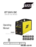
ET 201i DC

0-5452  

INTRODUCTION 

2-1

SECTION 2: 

INTRODUCTION

2.01  How to Use This Manual

This Manual usually applies to the part numbers listed on 

page i. To ensure safe operation, read the entire manual, 

including the chapter on safety instructions and warnings. 

Throughout this manual, the word WARNING, CAUTION 

and NOTE may appear. Pay particular attention to the in-

formation provided under these headings. These special 

annotations are easily recognized as follows:


NOTE!

An operation, procedure, or background informa-
tion which requires additional emphasis or is 
helpful in efficient operation of the system.

!


WARNING

A procedure which, if not properly followed, may 
cause injury to the operator or others in the operat-
ing area.

!


CAUTION

A procedure which, if not properly followed, may 
cause damage to the equipment.

WARNING
Gives information regarding possible electrical shock 
injury. Warnings will be enclosed in a box such as this.


DANGER
Means immediate hazards which, if not avoided, 
will result in immediate, serious personal injury or 
loss of life.

You will also notice icons from the safety section appear-

ing throughout the manual. These are to advise you of 

specific types of hazards or cautions related to the portion 

of information that follows.  Some may have multiple 

hazards that apply and would look something like this:

!

2.02  Equipment Identification

The unit’s identification number (specification or part 

number), model, and serial number usually appear on 

a nameplate attached to the machine. Equipment which 

does not have a nameplate attached to the machine is 

identified only by the specification or part number printed 

on the shipping container. Record these numbers for 

future reference.

2.03  Receipt of Equipment

When you receive the equipment, check it against the 

invoice to make sure it is complete and inspect the 

equipment for possible damage due to shipping. If there is 

any damage, notify the carrier immediately to file a claim. 

Furnish complete information concerning damage claims 

or shipping errors to the location in your area listed in the 

inside back cover of this manual.  Include all equipment 

identification numbers as described above along with a 

full description of the parts in error.

2.04 Description

The ET 201i DC is a compact inverter welding machine that 

has infinitely adjustable welding current from 10 to 200 

amps. It has LIFT TIG (GTAW) and HF TIG (GTAW) welding 

modes that offer stable TIG welding characteristics with 

an optimized start TIG sequence to initiate the welding arc 

when used with a suitable TIG torch and shielding gas. 
This model has advanced TIG features including an 8 Pin 

Amp Plug for remote control devices, down slope, 2T / 

4T controls, and gas solenoid operation. It also has a  

STICK (SMAW) welding mode which uses standard gen-

eral purpose STICK (SMAW) 3/32” (2.5mm) electrodes 

for light gauge work, generally less than 1/8” (3.2mm) 

thick and STICK (SMAW) 1/8” (3.2mm) electrodes for 

heavier material.

2.05  Transportation Methods

!


WARNING

Disconnect input power conductors from de-
energized supply line before moving the welding 
Power Source.
Lift Power Source with handle on top of case. Use 
handcart or similar device of adequate capacity. If 
using a fork lift vehicle, secure the Power Source on 
a proper skid before transporting.

Содержание ET 201i DC

Страница 1: ...Art A 13034 3163339 English Canadien Fran ais esab com ET 201i DC Inverter Arc Welder Operating Manual Revision AA Issue Date March 30 2016 Manual No 0 5452...

Страница 2: ...refore please take the time to read the entire manual especially the Safety Precautions They will help you to avoid potential hazards that may exist when working with this product YOU ARE IN GOOD COMP...

Страница 3: ...TX 76208 www esab com Copyright 2015 by ESAB All rights reserved Reproduction of this work in whole or in part without written permission of the publisher is prohibited The publisher does not assume...

Страница 4: ...ereof contained in this manual and accompany ing labels and or inserts when installed operated maintained and repaired in accordance with the instructions provided This equipment must be checked perio...

Страница 5: ...conform ment la description contenue dans ce manuel les tiquettes d accompagnement et ou les feuillets d information si l quipement est install op r entretenu et r par selon les instructions fournies...

Страница 6: ...em 3 9 3 09 LIFT TIG GTAW Setup 3 10 3 10 HF TIG GTAW Setup 3 12 3 11 When You Finish Using the Regulator 3 14 3 12 Storage of the Regulator 3 14 SECTION 4 OPERATION 4 1 4 01 Instruction 4 1 4 02 Fron...

Страница 7: ...ortion 4 12 4 23 Overcoming Distortion Effects 4 12 SECTION 5 SERVICE 5 1 5 01 Maintenance and Inspection 5 1 5 02 STICK SMAW Welding Problems 5 2 5 03 TIG Welding Problems 5 3 5 04 Power Source Probl...

Страница 8: ...TABLE OF CONTENTS This Page Intentionally Blank...

Страница 9: ...protected when the arc is struck 3 The workplace must be suitable for the purpose be free from drafts 4 Personal safety equipment Always wear recommended personal safety equipment such as safety glass...

Страница 10: ...ve clothing Protect bystanders with suitable screens or curtains FIRE HAZARD Sparks spatter can cause fire Make sure therefore that there are no inflammable materials nearby NOISE Excessive noise can...

Страница 11: ...eplate attached to the machine is identified only by the specification or part number printed on the shipping container Record these numbers for future reference 2 03 Receipt of Equipment When you rec...

Страница 12: ...6 4 Amps 12 3 11 1 Amps Maximum Input Current l1 max for STICK SMAW Welding 27 2 Amps 35 2 31 6 Amps Maximum Input Current l1 max for LIFT TIG HF TIG GTAW Welding 23 2 Amps 24 6 22 1 Amps Single Phase...

Страница 13: ...prove or revise the specifications or design of this or any product without prior notice Such updates or changes do not entitle the buyer of equip ment previously sold or shipped to the corresponding...

Страница 14: ...ET 201i DC INTRODUCTION 0 5452 2 4 This Page Intentionally Blank...

Страница 15: ...tance of the human body and the insulation properties of accessories Environments with increased hazard of electric shock do not include places where electrically conductive parts in the near vicinity...

Страница 16: ...connections should be made and inspection required The line disconnect switch provides a safe and convenient means to completely remove all electrical power from the welding power supply whenever nece...

Страница 17: ...A could occur if 253VAC or higher is applied to the Primary Power Cable Model Primary Supply Lead Size Factory Fitted Minimum Primary Current Circuit Size Vin Amps Current Duty Cycle LIFT TIG HF TIG G...

Страница 18: ...tection measures The size of the surrounding area to be considered will depend on the structure of the building and other activities that are taking place The surrounding area may extend beyond the bo...

Страница 19: ...reasing the risk of injury to users or damage to other electrical equipment Where necessary the connection of the work piece to earth should be made by direct connection to the work piece but in some...

Страница 20: ...trodes welding current at any one setting would vary according to the type of electrode in use The operator should use the welding current range values as a guide then fine tune the welding current to...

Страница 21: ...electrode manufacturer for specific polarity recommendations 3 Connect the ground work clamp to your workpiece 4 Plug the power cable into the appropriate outlet and turn the switch to the ON positio...

Страница 22: ...ng Pressure Gauges for Compressed Gas Service b Low pressure gauges must be UL recognized for the class of regulator they are being used on according to UL252A WARNING DO NOT use a regulator that deli...

Страница 23: ...equipment 3 08 Leak Testing the System Leak test the system before putting into operation 1 Be sure that there is a valve in the downstream equipment to turn off the gas flow 2 With the cylinder valv...

Страница 24: ...erminal Dinse 50 Negative Output Terminal Dinse 50 Art A 09785_AB Set Welding Current as specified by the Electrode Manufacturer Secure the gas cylinder in an upright position by chaining it to a stat...

Страница 25: ...be around the valve regulator seat area 5 Install the regulator for details of VICTOR regulator please refer to 3 07 and tighten with a wrench 6 Connect one end of the supplied gas hose to the outlet...

Страница 26: ...minal Dinse 50 Negative Output Terminal Dinse 50 Art A 10100_AB Set Welding Current as specified by the Electrode Manufacturer Secure the gas cylinder in an upright position by chaining it to a statio...

Страница 27: ...be around the valve regulator seat area 5 Install the regulator for details of VICTOR regulator please refer to 3 07 and tighten with a wrench 6 Connect one end of the supplied gas hose to the outlet...

Страница 28: ...ounterclockwise to release the ten sion on the adjusting spring 5 Check the gauges after a few minutes for verification that the cylinder valve is closed completely 3 12 Storage of the Regulator When...

Страница 29: ...it the specific application Refer to the electrode manufacture s literature for further information 4 02 Front Panel Front Panel The welding power source is protected by a self re setting thermostat T...

Страница 30: ...ontrol Knob F At any time while welding if the TIG Torch Trigger Switch is depressed and released the arc will extinguish immediately D Process Selection Switch Switches between STICK SMAW LIFT TIG GT...

Страница 31: ...y Voltage to the Power Source 4 03 Welding Current Control Explanation 15 Amp Outlet The mains power 15 Amp circuit breaker or fuse should not trip at this Weld Current value when STICK welding The en...

Страница 32: ...d by using the correct electrodes preheating using higher current settings using larger electrodes sizes short runs for larger electrode deposits or tempering in a furnace Manganese Steels The effect...

Страница 33: ...ogen all position electrode used when quality is an issueorforhard to weldmetals Ithasthecapabilityofproducing more uniform weld metal which has better impact properties at low temperatures Cast Iron...

Страница 34: ...35 50 Lap Filler 1 16 1 6mm 60 70 40 60 1 16 1 6mm 1 16 1 6mm 15 CFH 7 LPM Butt Corner 70 90 50 70 Lap Filler 1 8 3 2mm 80 100 65 85 1 16 1 16mm 3 32 2 4mm 15CFH 7 LPM Butt Corner 90 115 90 110 Lap Fi...

Страница 35: ...ertical position fillet weld Figure 4 9 Overhead position butt weld Art A 07687 Figure 4 3 Flat position down hand butt weld Art A 07688 Figure 4 4 Flat position gravity fillet weld Art A 07689 Figure...

Страница 36: ...lded should be clean and free of rust scale dirt grease etc Slag should be removed from oxy cut surfaces Typical joint designs are shown in Figure 4 11 Gap varies from 1 16 1 6mm to 3 16 4 8mm dependi...

Страница 37: ...iece This is caused by making too heavy a contact with the work and failing to withdraw the electrode quickly enough A low amperage will accentuate it This freezing on of the tip may be overcome by sc...

Страница 38: ...uent runs are then deposited using either a weave technique or single beads laid down in the sequence shown in Figure 4 14 The width of weave should not be more than three times the core wire diameter...

Страница 39: ...Figure 4 19 Examples of vertical fillet welds 2 Vertical Down The E7014 electrode makes welding in this position particularly easy Use a 1 8 3 2mm electrode at 120 amps The tip of the electrode is he...

Страница 40: ...line can be attempted hear 4 22 The Cause of Distortion Distortion is cause by A Contraction of Weld Metal Molten steel shrinks approximately 11 per cent in volume on cooling to room temperature This...

Страница 41: ...stortion Figure 4 24 shows a simple application By removing the heating source from b and c as soon as welding is completed the sections b and c will contract at a similar rate thus reducing distortio...

Страница 42: ...ET 201i DC OPERATION 0 5452 4 14 This Page Intentionally Blank...

Страница 43: ...solvents that are recommended for cleaning electrical apparatus CAUTION Do not blow air into the power supply during cleaning Blowing air into the unit can cause metal particles to interfere with sens...

Страница 44: ...se smaller diameter electrode C Allow wider gap D Use correct build up sequence 4 Portions of the weld run do not fuse to the surface of the metal or edge of the joint A Small electrodes used on heavy...

Страница 45: ...ing contaminates off B Check gas lines for cuts and loose fitting or change gas cylinder 8 Poor weld finish Inadequate shielding gas Increase gas flow or check gas line for problems 9 Arc flutters dur...

Страница 46: ...ary supply voltage has not been switched ON B The Welding Power Source switch is switched OFF C Loose connections internally A Switch ON the Primary supply voltage B Switch ON the Welding Power Source...

Страница 47: ...Dx6 ID W7003079 16 Connector Gas Outlet W7003212 17 Output Terminal 50mm dinse W7003020 18 Socket 8 Pin Cable W7003220 19 Gas Solenoid W7003033 20 Current Sensor W7003076 Current Sensor 21 Base Panel...

Страница 48: ...ET 201i DC KEY SPARE PARTS 0 5452 6 2 2 5 3 4 6 7 8 9 10 11 12 13 14 15 16 17 18 19 21 20 22 23 24 25 26 Art A 10104_AC 27 5 1...

Страница 49: ...ft 600285 Slider Current Control with Torch Switch 15ft suits 7 8 to 1 1 8 dia 17 TIG Torch Handle 10 4009 Slider Current Control with Torch Switch 15ft suits 1 1 8 to 1 3 8 dia 26 TIG Torch Handle 10...

Страница 50: ...OT MAX 4 POT MIN 5 6 START RTN 7 START 8 4 1 1 2 PANEL CUR DEMAND 3 4 10 CURRENT DEMAND 9 DOWN SLOPE ARC FORCE 8 2T 4T 7 N A 6 FAULT LED 5 HF TIG 4 STICK 3 VOLTAGE TEST 2 15VDC 1 15VDC 1 10 1 RED BLAC...

Страница 51: ...This Page Intentionally Blank...

Страница 52: ...95 00 Fax 46 31 50 92 22 ESAB international AB Gothenburg Tel 46 31 50 90 00 Fax 46 31 50 93 60 SWITZERLAND ESAB AG Dietikon Tel 41 1 741 25 25 Fax 41 1 740 30 55 UKRAINE ESAB Ukraine LLC Kiev Tel 38...

Отзывы: