


6 CONTROL PANEL
0463 703 001
GB
-38-
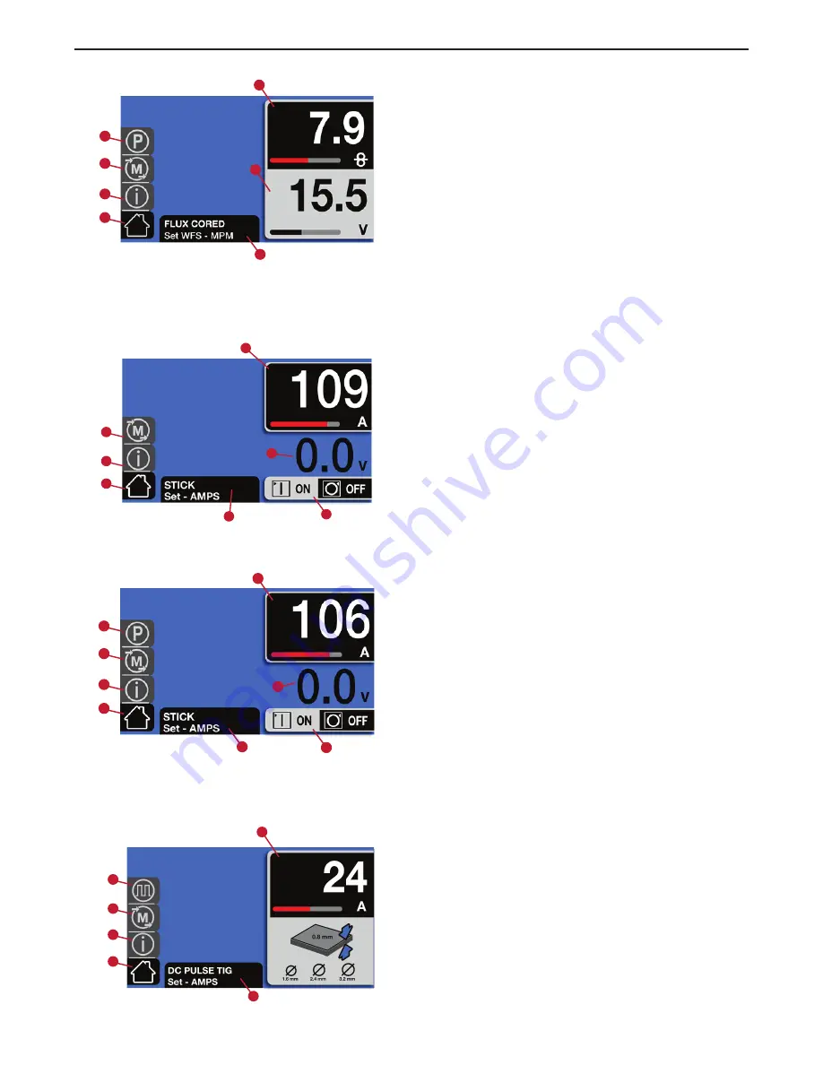
• Advanced:
1. Home screen
2. Information
3. Memory
4. Parameter selection
5. Wire-feed speed
6. Voltage adjustment
7. Dialogue box
6.2.4
MMA mode
• Basic:
1. Home screen
2. Information
3. Memory
4. Amperage adjustment
5. Weld output voltage
(Open Circuit Voltage or Arc)
6. Dialogue box
7. Arc ON/OFF
Blue changes to orange when output is "hot".
• Advanced:
1. Home screen
2. Information
3. Memory
4. Parameter selection
5. Amperage
6. Weld output voltage
(Open Circuit Voltage or Arc)
7. Arc ON/OFF
8. Dialogue box
Blue changes to orange when output is "hot".
6.2.5
DC TIG mode
• Basic:
1. Home screen
2. Information
3. Memory
4. Pulse
5. Amperage
6. Dialogue box
5
6
3
4
2
1
7
5
6
3
4
2
1
7
5
6
3
4
2
1
7
8
5
3
4
2
1
6


