


OPERATION
48
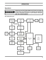
sequence of operation
The EPP-202 has no power switch installed in the unit. The wall breaker is the power disconnect for this power
supply. Once the wall breaker is closed, the following events occur:
1. Power is applied to the control transformer T2. This supplies power to the circuit boards - PCB1 the Con-
trol board and PCB2 the Driver board. Main micro on the control board (PCB1) establishes the digital
communication with CNC/Process Controller through CAN or analog interface through DB25 connector.
2. Pump Motor (M2) turns ON. Coolant pumps out to the torch and comes back into the tank through radia-
tors, filter, flow sensor, and IGBTs cold plate respectively.
3. The Control board performs a fault/error check. If there are no faults/errors the power up sequence will
continue.
4. Power Light (PL) on the front panel will be ON all time indicating there is input power available and Fault
Light (FL) will be OFF indicating there are no faults/errors.
5. The power supply enable relay K4 will close if there are no errors/faults in the power source and there is
no interruption in PS Enable chain on the cutting machine.
6. If above steps are satisfied then the Bus Pre-Charge contactor (K2) closes and charges the Bus Filter Ca-
pacitor (C1) through a 2-Ohm resistor in each phase.
7. Once bus is pre-charged to a threshold of 200 VDC then control baord issues the command to close the
Main contactor (K1), Main Fan Motor (M1) and open K2. This will allow the bus filter capacitor to charge up
to the full voltage of 360 VDC.
8. The bus will be high as soon as the wall breaker closed and there are no faults in the power supply. K1
and M1 will stay ON for 5 minutes of Idle operation and then they will turn OFF, hence bus filter capacitor
voltage bleed through R8 (3 kOhm, 100W) resistor.
When the EPP-202 is commanded to start the plasma cut process, the following events occur:
1. Once a start signal is sent, if bus is not high, a soft start sequence begins. The main control board (PCB1) is-
sues the command to close the bus pre-charger relay K2. This signal is sent to the Relay Block Module (RB1)
through ribbon cable connector J6. On the relay block module relay one (RB1-1) is energized. This passes
24 VAC to the coil of K2, the soft start relay. This puts main line power to the Main Transformer (T1) with a 2
ohm resistor in series (with each phase) to initially limit the amount of current. This is done for two reasons:
a. Due to the large input filter capacitors, a very large current would be seen on the output of the main
transformer.
b. To limit current in case there is a short on the rectifier, the capacitors, or the transformer.
2. After K2 is closed, PCB1 monitors the bus voltage across C1. The main-micro on PCB1 looks for bus filter
capacitor voltage to reach +200 VDC or 500 ms time out. If +200 VDC is present, the micro initiates com-
mands to pull in the main contactor K1, turn ON main fan (M1) and then open K2. After K1 is pulled in, the
power supply waits few milliseconds for the bus to reach its full voltage of 360VDC. If bus filter capacitor
voltage does not reach +200 VDC before 500 ms timer time out then power supply will send Error 15 to
CNC/Process Controller via CAN and toggle the Fault Light (FL) on front panel with 50% duty cycle.
3. Once bus is fully charged and main-micro read all the respective currents and ramping times from CNC/
Process Controller through CAN communication, main-micro will issue the PWM start signal to servo-micro
which then will provide 25 KHZ frequency pulses to IGBTs. At this point main-micro monitors the Open
Circuit Voltage (OCV) on the output, which should be at least 280 VDC for a period of 200 ms. If this fails
then power supply will shutdown, toggles the fault light and sends Error 13 to the CNC/Process Controller.
4. If proper OCV is read main-micro sends command to close HF relay which will provide 115 VAC to HF cir-
cuit in the RAS box and sends pilot arc enable signal to servo-micro which then will provide PWM signal
to pilot arc IGBT (Q5). If HF is present at the torch, Pilot Arc is established.
Содержание 0558011310
Страница 2: ...EPP 202 Plasma Power Source 2...
Страница 4: ...EPP 202 Plasma Power Source 4...
Страница 7: ...SAFETY...
Страница 8: ...SAFETY 8...
Страница 21: ...DESCRIPTION...
Страница 22: ...description 22...
Страница 25: ...INSTALLATION...
Страница 26: ...installation 26...
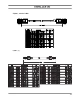
Страница 39: ...installation 39 J1 RAS Interface Cable CAN Cables...
Страница 40: ...installation 40...
Страница 41: ...OPERATION...
Страница 42: ...OPERATION 42...
Страница 50: ...OPERATION 50...
Страница 51: ...MAINTENANCE...
Страница 52: ...Maintenance 52...
Страница 57: ...TROUBLESHOOTING...
Страница 58: ...58 TROUBLESHOOTING 58...
Страница 65: ...REPLACEMENT PARTS...
Страница 66: ...Replacement Parts 66...
Страница 68: ...Replacement Parts 68...
Страница 69: ...revision history 1 Originally released 01 2015 2 Revision 10 2015 added RotorFlow Sensor...


