


11
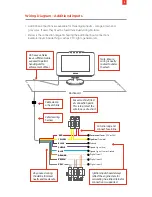
Wiring Diagram – Additional inputs
YELLOW
Switched
Power (Engine on/off)
Permanent
Power (12V or 24V)
Ground
Digital input 2
Digital input 3
BLACK
ORANGE
BROWN
GRAY
RED
Digital input 1
IG
N
+
ve
3A
3A
3A
PURPLE
Speed Signal (+ve)
BLUE
Speed Signal (-ve) or Ground
• Additional connections are available for three digital inputs – orange, brown and
gray wires. If used, they must be fused individually using 3A fuses.
• Below is the connection diagram showing the additional input connections.
Example inputs include things such as PTO, lights, generator etc.
Permanent
Power (12V or 24V)
Ignition
(True Idle)
Ground
Speed Signal (+ve)
Speed Signal (-ve) or Ground
Digital Input 1
Digital Input 2
Digital Input 2
RED
YELLOW
BLACK
PURPLE
BLUE
ORANGE
BROWN
GRAY
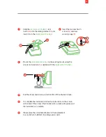
Any unused wiring
should be trimmed
neatly and made safe
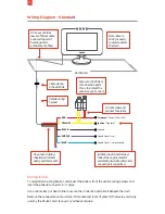
Dashboard
Fuses must be fitted
at connection point.
This is to protect the
wire in case of a short
Cut wire loop and
connect fuse inline
Cable clamp
or heat shrink
Vehicle wiring
harness
Note: Ensure
wiring is neatly
routed to under
the dash
RAM
EROAD
Ignition input should always
reflect the engine state for
calculating true idle. Alternator
connection is supported
On heavy vehicles
leave sufficient cable
exposed to permit
handing unit to
enforcement officer
Содержание ehubo2
Страница 1: ...EROAD Ehubo2 Installation Guide...
Страница 15: ...16 INNOVATION AND INTEGRITY EROAD COM...