


High-Speed Drum: Model DF
7
Magnet Rotation
On the drum shaft there is either an arrow indicating
the center of the magnet arc or a colored section
indicating the magnet arc. The normal position for the
magnet element has the arc center slightly elevated
in the front half of the drum. The drums are usually
shipped with the magnet arc hanging down and
must be repositioned for startup.
The magnetic material will stand up in the center
of a magnetic pole where the field is perpendicular
to the material flow. At the pole edge the magnetic
material will lay down and point towards the next pole
or away from the magnet arc almost tangent to the
drum surface. Sometimes this pole edge can be seen
as a line of magnetics before a drum cleat wipes the
magnetics away.
The splitter tip will separate magnetics better if it is
located between the pole edges, rather than in the
center of a pole. If the edge can be seen, the splitter
tip can be adjusted accordingly. However, sometimes
the splitter cannot be adjusted to the optimum length.
In this case, the magnet rotation can be adjusted by
loosening the set screws on the flange mounted on
the non-drive side of the drum. The magnet adjusting
arm turnbuckle is used to adjust the magnet to fit the
splitter position and the set screws re-tightened.
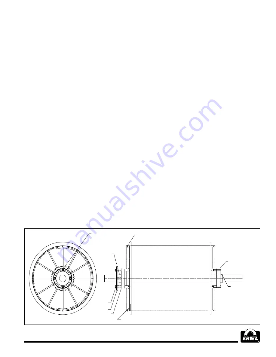
Bearing Replacement
The standard units have four bolt flange bearings
which are sealed and greaseable. Remove the drum
from the housing. Support the drum shaft on blocks to
take the weight of the bearings. When removing the
bearings you should first clean the shaft thoroughly
with solvent then attempt to remove the four bearing
mounting bolts and bearings set screws.
Pry between the bearing and the drum head to slide
the bearing off the end of the shaft. If the bearing is
not moving (usually due to the head flexing inward),
you will have to remove all the fasteners holding the
drum head to the shell.
You would then use the tapped holes in the head with
threaded rod and porta power pushing against the
end of the shaft. Make sure to match mark the heads
and shell before going this route. (See Figure 5)
To Install a New Bearing
1. Inspect the shaft. Remove burrs, verify diameter
and clean mounting surface.
2. Place bearing on the shaft. Apply light film of oil.
Do not hammer onto shaft.
3. Bolt housing to mounting surface. Make sure the
magnetic element is centered between the heads.
Rotate shaft to make sure it turns smoothly.
4. Bolt up the bearing to the mounting surface and
torque bolts to 75 ft.-lbs.
5. With two setscrews, torque set screw ‘A’ to ½
recommended torque (73-95ft.-lbs.), torque set
screw ‘B’ to full torque. Torque setscrew ‘A’
to full torque.
Figure 5
Flange bearing bolts
Bearing
set screws
use blue
loctite
Fasteners holding
head to shell
Flange bearing
Spot shaft @
assembly four
locations
Drum head
Flange bearing
max T.I.R.
sprocket .020"
Sprocket
Torque to
75 ft lbs
use blue
loctite


