Installing the Hardware
2.4.1.1
Connect Power Cables
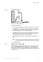
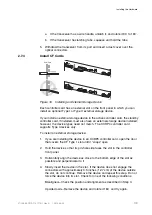
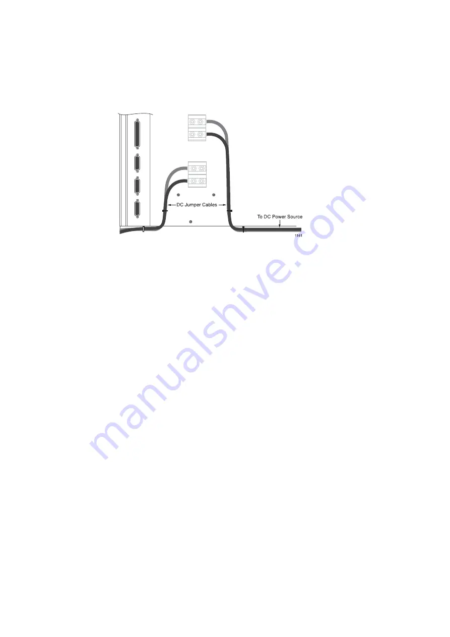
Figure 6
DC Power Connections
Connect the power cables:
1.
Using a crimping tool, attach a two-hole lug to one end of each power cable.
2.
For the BATTERY A connection, secure the connection of the red cable to
RETURN with a pair of lug nuts and the black cable to -48V; tighten to a
maximum torque of 15.0 inch-lbs (1.7 Newton-meters).
3.
For the BATTERY B connection, secure the connection of the red cable to
RETURN with a pair of lug nuts and the black cable to -48V; tighten to a
maximum torque of 15.0 inch-lbs (1.7 Newton-meters).
4.
Use the provided metal loops in the chassis to dress the cables with tie
wraps.
5.
Note:
The dressing of the DC jumper cables must allow for servicing the
push-through air filter and the fan tray from the rear of the chassis.
6.
Install the safety cover.
2.5
Optional AC Power Shelf
The optional AC power shelf provides slots for two AC power modules, which
allows a SmartEdge 600 router to be installed at a site for which DC power
sources are not available. AC power shelf connects to the SmartEdge 600
chassis with two pairs of DC jumper cables using connectors on the rear of the
AC power shelf.
27
27/153 30-CRA 119 1170/1 Uen A
|
2010-04-09
Содержание SmartEdge 600
Страница 1: ...SmartEdge 600 Router Hardware Guide Release 6 3 INSTALLATION 27 153 30 CRA 119 1170 1 Uen A ...
Страница 6: ...SmartEdge 600 Router Hardware Guide 27 153 30 CRA 119 1170 1 Uen A 2010 04 09 ...
Страница 26: ...SmartEdge 600 Router Hardware Guide 20 27 153 30 CRA 119 1170 1 Uen A 2010 04 09 ...
Страница 108: ...SmartEdge 600 Router Hardware Guide 102 27 153 30 CRA 119 1170 1 Uen A 2010 04 09 ...
Страница 112: ...SmartEdge 600 Router Hardware Guide 106 27 153 30 CRA 119 1170 1 Uen A 2010 04 09 ...

