Connecting and Routing the Cables
Installing the Hardware
4-31
Connect and Route the Cables at the Front of the Chassis
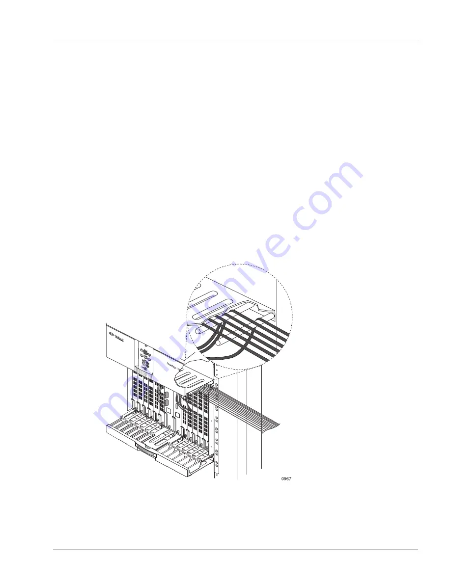
With the exception of the breakout cables for FE-GE traffic cards, you route the copper cables upward,
using the cable bars on the underside of the fan tray to separate the cables for each card. After all copper
cables are routed, you route the fiber-optic cables, using the cable guides in the cable tray to separate the
cables for each card. After you have routed all other cables, you route the breakout cables for the FE-GE
traffic cards. Cable connections are made with standard cables. Appendix A, “Cables and Pin
Assignments,” describes the standard SmartEdge 1200 cables and pin assignments.
Perform the following steps to connect and route the cables at the front of the chassis:
1. Connect and route the copper cables; see Figure 4-25:
a. Insert each cable into the appropriate connector on the card.
b. Starting with the cards installed in the inner slots (4 to 7 and 8 to 11), insert the cables for a card
between the two cable bars for that card on the underside of the fan tray.
c. With the cables resting on top of the cable bars, slide them to the outer edge of the fan tray.
d. Tie-wrap the bundled cables from each card to the outside edge of the rack.
e. Continue routing all copper cables, working toward the outer slots (1 to 3 and 12 to 14).
Figure 4-25
Copper Cable Routing
Содержание Redback Networks SmartEdge 1200
Страница 6: ......
Страница 28: ...System Components 1 14 SmartEdge 1200 Router Hardware Guide...
Страница 60: ...Gathering Cables and Tools 3 16 SmartEdge 1200 Router Hardware Guide...
Страница 166: ...Traffic Card Cables A 10 SmartEdge 1200 Router Hardware Guide...


