background image


PSIG Support


I.1 

Program Specific Information Generator (PSIG) 

The PSIG interface is a ETSI defined spec that enables PSI/SI to be inserted in the 
output transport streams of the MX8400. It is defined in ETSI TS 103 197 in 
Section 9. 

The main function of the (P)SIG is to provide MUXes of the head-end with the 
appropriate PSI/SI tables for their respective transport streams. Additionally, private 
sections may possibly come with the PSI/SI tables so as to be broadcast with the 
same PID(s). 

The (P)SIG may have to deal with more than one MUX and so may have to 
generate specific tables for more than one transport stream. Nonetheless, each 
MUX gets its PSI/SI from only one unique (P)SIG. 

I.2 

Why do I Need PSIG? 

If you don't want to use nCompass Control (nCC) to generate PSI/SI or additional SI 
is to be added from an external source. It can work with nCC and other external 
PSI/SI sources that are using the Ericsson RCP interface simultaneously. 

I.3 

Static Parameters 

I.3.1 

Using PSIG 

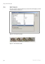
The MX8400 implements the PSIG interface as defined in ETSI TS 103 197. 

There are currently no deviations from the spec. The MX8400 allows 32 PSIG 
connections on the Control IP port. These are defined in Static Parameters using the 
nCC physical map. 

2/1553-FGC 101 1014 Uen B


I-3


Содержание MX8400

Страница 1: ...MX8400 Multiplexer Software Version 5 2 0 and later REFERENCE GUIDE 2 1553 FGC 101 1014 Uen B...

Страница 2: ...r pria custa DANSK L S DETTE F RST Udstyret m ikke betjenes MEDMINDRE DE TIL FULDE FORST R INDHOLDET AF DENNE H NDBOG Vi kan ogs for Deres regning levere en dansk overs ttelse af denne h ndbog FRAN AI...

Страница 3: ...censes Chapter 4 Operating the MX8400 Multiplexer using nCompass Control This chapter describes how to set the IP address of the MX8400 Multiplexer to allow it to connect to nCompass Control Chapter 5...

Страница 4: ...tware Version Comments 1 Feb 2009 2 0 0 RJ 45 Ethernet Option Card with PRO MPEG FEC added 2 Nov 2009 3 0 0 SFN functionality added and associated GPS Interface card supported Missing PID Monitoring s...

Страница 5: ...in the next issue of this Reference Guide Some trademarks may be registered in some jurisdictions but not in others Registered trademarks and trademarks used are acknowledged below and marked with th...

Страница 6: ...injury or death or damage to property or the environment They are highlighted for emphasis as in this example and are placed immediately preceding the point at which the reader requires them Caution...

Страница 7: ...vantage These packages are designed to save you costs and protect your income through enlisting the help of Ericsson support specialists Call Ericsson Sales for more details Customer Services Europe M...

Страница 8: ...rategic Park Comines Way Hedge End Southampton Hampshire SO30 4DA United Kingdom Return of Equipment If you need to return equipment for repair please contact your local Ericsson Customer Services Dep...

Страница 9: ...5 TS IP Summary of Features 1 8 1 3 2 6 ASI Input Output Summary of Features 1 8 1 3 2 7 Dual PSU 1 9 1 3 3 Remote Reflex 1 9 1 3 3 1 Statistical Multiplexing 1 9 1 3 3 2 Remote Statistical Multiplex...

Страница 10: ...ure 1 3 Current Label Affixed to the rear of the unit 1 5 Figure 1 4 The Role of the MX8400 Multiplexer in a Cable Distribution System 1 12 Figure 1 5 Front Panel Indicators 1 13 Figure 1 6 Typical Re...

Страница 11: ...of the unit Maintenance information that requires covers to be removed is not included Warning Do not remove the covers of this equipment Hazardous voltages are present within this equipment and may...

Страница 12: ...able 1 2 Software License Key Descriptions Marketing Code MX8400 SWO MUX DVBCA DVBCA EXT SFN Option Additional Multiplexed Output DVB CA Base Option Additional DVB CA System Support Additional SFN Cap...

Страница 13: ...Serial Number A unique number for unit Bar Code Used for unit identification in the manufacturing process Equipment Number and Product Type 8000 MULTIPLEXER S N TB46323 KDU XXX XXX X 1 2 3 2 Firmware...

Страница 14: ...which the output rate of a transport stream can be set by entering a bit rate is 1 bps The output bit rate can be set exactly to any of the DVB T modes SFN adapter functionality is included to produc...

Страница 15: ...rcing any transport streams missing from the primary network from the secondary network without affecting any other active service Refer to Annex E Redundancy Modes for further details The MX8400 supp...

Страница 16: ...ion on board clock if no external source is available Dual HSYNC clock inputs support the option of locking an internal frequency reference to an external studio clock The external clock reference is...

Страница 17: ...on s implementation of statistical multiplexing and is associated with a multiplexer being co sited with the encoder sourced services Remote Reflex is used when services are sourced from encoders whic...

Страница 18: ...ween V4 Reflex status reports from encoder 400 ms 133 ms V1 Reflex Update Rate The rate times sec at which set bit rate messages are sent to V1 Reflex encoders 25 s 30 s Encoder Wait Time For V1 refle...

Страница 19: ...s will be rejected it must be a 12 character hex string Individual transport streams can be scrambled simultaneously with either DVB CA or BISS but not individual components The MX8400 will only suppo...

Страница 20: ...ble distribution scheme Figure 1 4 The Role of the MX8400 Multiplexer in a Cable Distribution System 1 4 2 MX8400 Multiplexer Control Using nCompass The MX8400 Multiplexer is designed for unattended o...

Страница 21: ...Lit Comment Left Alarm Red On Multiplexer general alarm Middle Power Green On Power is applied to the unit Right Active Blue Off On Redundant Active Used in redundancy systems Figure 1 5 Front Panel I...

Страница 22: ...Rear Panel Indicators Figure 1 7 shows the position of the rear panel indicators on the Multiplexer Card Figure 1 7 Rear Panel Indicators Indicators associated with the Ethernet interface RJ 45 connec...

Страница 23: ...on 2 8 2 3 7 1 Airflow 2 8 2 3 7 2 Temperature Monitoring 2 9 2 4 EMC Compliance Statements 2 9 2 4 1 EN 55022 AS NZS 3548 2 9 2 4 2 FCC 2 9 2 5 Connecting up the MX8400 Multiplexer 2 10 2 6 AC Supply...

Страница 24: ...2 24 2 11 1 Overview 2 24 2 11 1 1 Functional Description 2 24 2 11 1 2 Indicators 2 24 2 11 2 Static Parameters 2 25 2 11 2 1 Overview 2 25 2 11 2 2 ECMGs Table 2 26 2 11 2 3 Reported Faults 2 26 2 1...

Страница 25: ...ons 2 18 Table 2 6 Output Mode Configurations 2 19 Table 2 7 Static Parameters Data Port Table 2 20 Table 2 8 Static Parameters Editing Data Port IO Mode 2 21 Table 2 9 Ethernet Input Reported Faults...

Страница 26: ...Installing and Powering Up 2 1553 FGC 101 1014 Uen B 2 4 BLANK...

Страница 27: ...e in ambient air temperature conditions in the range 0 C to 50 C and humidity 0 to 95 non condensing See Annex B Technical Specification for a full specification Do not install this product in areas o...

Страница 28: ...quipment may fall causing serious injury and serious damage to the equipment Use only with a cart stand bracket or table recommended by Ericsson An appliance and cart combination should be moved with...

Страница 29: ...sure that the equipment is firmly and safely located and has an adequate through flow of air The equipment must be installed and operated in the normal horizontal orientation i e not inverted or stand...

Страница 30: ...adhered to Do not install equipment so that the air intake of one aligns with the outlet on another Provide baffles and adequate spacing The fans contained within this unit are not fitted with dust an...

Страница 31: ...Compass Control to trigger a change over to a standby MX8400 Multiplexer The relay is non latching and will revert to its normal state when the fail condition is corrected 2 4 EMC Compliance Statement...

Страница 32: ...age Fusing and Earthing 2 6 1 AC Supply Warning Do not overload wall outlets and extension cords as this can result in a risk of fire or electric shock Caution This product should be operated only fro...

Страница 33: ...nd Fault finding for the fuse replacement procedure Fuse Carrier 2 6 3 Power Cable and Earthing 2 6 3 1 General Check that the AC supply cable is suitable for the country in which the equipment is to...

Страница 34: ...White Live L Brown Brown Black 2 6 4 Protective Earth Technical Earth 2 6 4 1 General Warnings This equipment must be correctly earthed through the moulded plug supplied If the local AC supply does n...

Страница 35: ...upply cord The equipment is not fitted with an ON OFF switch Ensure that the socket outlet is installed near the equipment so that it is easily accessible Failure to isolate the equipment properly may...

Страница 36: ...correct cables are used when interconnecting to other equipment Annex B Technical Specification provides a table detailing the cable types as recommended by Ericsson If further details are required pl...

Страница 37: ...output 1 HSYNC analogue output 2 RJ 45 TS Data Port GbE RJ 45 TS Data Port GbE RJ 45 TS Data Port GbE RJ 45 TS Data Port GbE Conditional Access Conditional Access Control Port 10 100 nCC Control Port...

Страница 38: ...2 HSYNC OUT 2 BNC Page 2 30 3 Data 1 4 Data 2 5 Data 3 6 Data 4 RJ 45 Left Off No output Green Full duplex Yellow Half duplex Right Green 100 Mbps Yellow 1000 Mbps Page 2 17 7 CA 1 8 CA 2 RJ 45 Left O...

Страница 39: ...ew 2 8 1 1 Port Configurations There are four dedicated IP GbE interface ports using RJ 45 connectors Using nCompass Control the MX8400 IP GbE interface ports can be configured as detailed in Table 2...

Страница 40: ...ted input and output data networks There are two possible configurations that map the ports as input or outputs The MX8400 data paths configurations for such system are described in Table 2 5 These ar...

Страница 41: ...3 Mirrored Both outputs are used at the same time The same data appears on both the output ports Input Input Output Output 2 8 2 Static Parameters 2 8 2 1 Data Ports When this entry in the Static Par...

Страница 42: ...is not currently supported 2 8 2 2 Data Port IO Mode Data Port IO Mode Value TABLE Click on the table to display a list of Card Nos actually corresponds to Slot numbers Figure 2 8 Static Parameters D...

Страница 43: ...ults Fault Level Network input link lost Major All network input links lost Critical Port CRC error Warning Port IP checksum error Warning Port UDP checksum error Warning Network output link lost Majo...

Страница 44: ...ode These two data inputs are usable concurrently A bit rate range of 1 72 Mbps for byte mode and 1 213 Mbps for packet mode and 188 204 byte operation on each input are supported 2 9 1 2 Connectors T...

Страница 45: ...o 4 2 10 1 Overview 2 10 1 1 Functional Description These four connectors provide asynchronous serial interface ASI outputs The output is automatically set to byte mode burst mode depending on bit rat...

Страница 46: ...be supported concurrently Simulcrypt These ports are the CA management interface and are used to control the internal Conditional Access function The scrambling engine can support rates up to 1 Gbps N...

Страница 47: ...Parameters CA Name Description Value CA1 IP Address IP settings for CA port 1 10 1 101 6 CA 1 Subnet IP settings for CA port 1 255 255 255 0 CA2 IP Address IP settings for CA port 2 10 1 101 7 CA 2 Su...

Страница 48: ...ork External means use the CA network 0 2 11 2 2 ECMGs Table Figure 2 9 shows the Editing ECMG page Figure 2 9 Editing ECMGs 2 11 2 3 Reported Faults Table 2 18 describes the reported faults associate...

Страница 49: ...e control connection Table 2 19 Ethernet Control 1 and 2 Connectors 1 8 Item Specification Connector type RJ 45 Connector designation ETHERNET 1 ETHERNET 2 Pin Unused pins not connected Pin 1 Tx Out P...

Страница 50: ...5 255 0 Control2 IP Address IP setting for control port 2 192 168 0 221 Control 2 Subnet IP setting for control port 2 255 255 255 0 Control Float IP Address IP settings for the floating control port...

Страница 51: ...n 9 5 V through Fault relay 0 V through 5 Alarm Contacts Pin 2 Pin 3 Pin 4 Alarm Common 5 in series Make to pin 2 when OK Make to pin 2 when not OK Fail Contacts Pin 6 Pin 7 Pin 8 Make to pin 8 when O...

Страница 52: ...t does not impact on the output services The MX8400 switches back to the primary input when reconfigured by the user or if the secondary input fails Table 2 24 HSYNC IN Item Specification Connector ty...

Страница 53: ...iated with the HSYNC function Table 2 27 Static Parameters HSYNC Name Description Value Reference Clock Source Internal HSYNC analogue black and syncs or GPS External Reference Clock Type NTSC PAL whe...

Страница 54: ...the following 1 The equipment has been installed in a suitable location 2 The power supply has been checked and a good earth provided 3 The correct fuse type and rating has been fitted to both the eq...

Страница 55: ...rom nCompass Control This is indicated by the Alarm indicator extinguishing If the test result is a FAIL the MX8400 Multiplexer remains in the self test mode with the inputs disabled The Fail relay is...

Страница 56: ...or supplies if dual PSUs are fitted to remove power from the equipment The product configuration is non volatile the unit is able to reboot after a power failure and output a correctly configured tra...

Страница 57: ...ntroduction 3 9 3 3 1 2 ProMPEG FEC 3 9 3 3 1 3 Input Ports 3 9 3 3 1 4 Output Ports 3 11 3 3 1 5 License Information 3 11 3 3 2 Connectors 3 11 3 3 3 nCompass Control v6 3 Associated Menus 3 12 3 3 3...

Страница 58: ...st of Tables Table 3 1 Hardware Option Modules 3 3 Table 3 2 Purchasable Software Options 3 4 Table 3 3 ASI Module Indications 3 5 Table 3 4 MX8400 HWO xASI Option Module Properties Page Parameter Des...

Страница 59: ...rdware Option Modules Marketing Code MX8400 HWO 4ASI 8ASI PROFEC GPS Name 4 Port ASI Option Card 8 Port ASI Option Card RJ 45 Ethernet Option Card with ProMPEG FEC GPS Interface Unit Option Slot Any 2...

Страница 60: ...tiplexer configuration to be investigated In the physical map display left click on a Multiplexer icon and select properties from the displayed context sensitive menu This displays the properties page...

Страница 61: ...show the rear panels of the two types of ASI Option module Figure 3 2 MX8400 HWO 4ASI Rear Panel Figure 3 3 MX8400 HWO 8ASI Rear Panel All single ASI TS physical inputs provide a visual indication as...

Страница 62: ...giving information associated with the selected device Alternatively right click a device icon in the Device Tree pane or on the physical map to display a context sensitive menu Select Properties to...

Страница 63: ...t ports for the MX8400 HWO 8ASI option card The MX8400 HWO 4ASI option card 4 has a similar display but only has four ASI IN OUT ports 3 2 4 Technical Specification 3 2 4 1 ASI IN Table 3 5 MX8400 HWO...

Страница 64: ...ass Control Table 3 6 MX8400 HWO xASI Transport Stream Output Item Specification Safety status SELV Connector type BNC Connector Impedance 75 Data coding 8B 10B Channel rate 270 Mbps Supported Packet...

Страница 65: ...d Redundancy is detailed in Annex E Redundancy Modes 3 3 1 2 ProMPEG FEC This option card can provide up to 32 input streams with FEC in accordance with ProMPEG Code of Practice No 3 as a user configu...

Страница 66: ...ge Latency dependent on frame rate i e data rate and packets per frame example latencies excluding Remote Reflex mode see Table 3 7 Table 3 7 Latency vs Frame Rate Packets Per Frame Bit Rate bps 1 4 7...

Страница 67: ...packets per frame Note This implies that all interfaces are carrying the same output data The maximum output rate not including FEC overhead for a single transport stream is 250 Mbps 3 3 1 5 License I...

Страница 68: ...ssociated Menus 3 3 3 1 MX8400 Properties Page Double click a device icon in the nCompass Equipment Set up Device Tree pane or on the physical map to display the Properties dialog box giving informati...

Страница 69: ...s Page with an MX8400 HWO PROFEC Option Module Fitted 3 3 3 2 MX8400 HWO PROFEC Option Module Drop down Dialog Boxes Figure 3 7 shows the MX8400 Properties Page with the MX8400 HWO PROFEC Option Modul...

Страница 70: ...PEG FEC Card These are listed on the Ports Page Each port requires configuring to enable it to function Each port requires multicast IP port settings in order to operate correctly 3 3 3 3 MX8400 HWO P...

Страница 71: ...Hardware Options and Software Licenses Figure 3 8 MX8400 HWO PROFEC Option Module Transport Stream Settings 2 1553 FGC 101 1014 Uen B 3 15...

Страница 72: ...nce ETSI TS 103 197 V1 4 1 DVB CSA The MX8400 BAS CA engine supports DVB CSA scrambling A software license is required to enable SimulCrypt MX8400 SWO DVBCA A software license MMX8400 SWO DVBCA EXT is...

Страница 73: ...used until a key is available The multiplexer is able to generate CAT s and PMT descriptors for the encrypted stream s 3 5 GPS Interface Module MX8400 HWO GPS 3 5 1 Overview 3 5 1 1 Functional Descrip...

Страница 74: ...Interface Rear Panel 3 5 1 3 Input Signal Characteristics The GPS Interface Module accepts signals with the following characteristics Table 3 12 GPS Interface MX8400 HWO GPS Pulse Parameters Input Con...

Страница 75: ...le Locking of the Multiplexer clock to GPS 10 MHz is selected using static parameters see Annex C Static Parameters under reference clock option The options are similar to HSync redundant revert etc O...

Страница 76: ...Certain functionality of the unit is dependent upon the specific model the hardware options fitted and the software options installed in it Software options are enabled or disabled by means of license...

Страница 77: ...2 Allocation of Bit rates 4 7 4 5 4 Statistical Multiplexing Reflex 4 7 4 5 4 1 Advantages of Statistical Multiplexing 4 7 4 5 4 2 Role of the MX8400 Multiplexer in Statistical Multiplexing 4 7 4 5 4...

Страница 78: ...3 ASI Monitoring for each Multiplexer Output Transport Stream 4 14 Figure 4 4 PSI SI Remultiplexing 4 15 Figure 4 5 Clone a TS in the Clear 4 17 List of Tables Table 4 1 Local 1 Connector 4 3 Table 4...

Страница 79: ...4 1 2 IP Address Use the setip command to configure the IP address of each of the multiplexer s control Ethernet ports via the RS 232 terminal Table 4 2 shows user entries and returned messages for t...

Страница 80: ...2 MPEG 4 DVB compliant equipment such as Receivers Decoders Descramblers Encoders Multiplexers and Modulators with third party ECM EMM generators and switches into one manageable digital TV broadcast...

Страница 81: ...rameters 6 The dynamic parameters are all configured using nCompass Control s Profile Manager For further details refer to the nCompass Control manual 4 4 Configuring the MX8400 Multiplexer 4 4 1 Defi...

Страница 82: ...n the simplest mode of operation called conventional multiplexing nCompass Control allocates a fixed bit rate to each Encoder The Operator can use the display from nCompass Control to manually alter a...

Страница 83: ...avoid compression artefacts The fixed bit rate is therefore set at the level required to satisfy peak demands This leads to the non optimal use of the channel capacity 4 5 4 Statistical Multiplexing...

Страница 84: ...ces Exploits the likelihood that peaks in demand are infrequent on any single channel 4 5 5 Using Statistical Multiplexing 4 5 5 1 Introduction The following information explains the use of statistica...

Страница 85: ...576 News Channel 3 0 4 352 x 576 Film Channel 2 0 TOTAL 15 0 The more Encoders there are in a group the more potential there is to reduce the group bit rate although this may have to be modified in th...

Страница 86: ...576 544 x 480 8 0 Mbps 480 x 576 480 x 480 7 0 Mbps 352 x 576 352 x 480 6 0 Mbps 544 x 288 4 0 Mbps 480 x 288 3 5 Mbps 352 x 288 3 0 Mbps 4 5 5 5 Group Performance 4 5 5 5 1 Defining the Term The Grou...

Страница 87: ...demanded by others in the group Table 4 8 shows the situation where channels 1 and 2 are protected Table 4 8 Example of Protected Channels Ch Resolution and Material Type Weighting Avg Bit rate Min Bi...

Страница 88: ...utput on the nCompass Control Equipment Setup Physical Map New devices are added to an exisitng or new map by selecting an icon from the Device Types list in the right hand pane and dragging and dropp...

Страница 89: ...ist select Outputs Displays a list of available output types This may be hardware dependent 2 From the list select Generic Output Highlights the Generic Output icon 3 Drag and drop the icon onto the m...

Страница 90: ...t TS1 Monitoring Output TS2 4 8 2 Setting up the Monitoring 4 8 2 1 Procedure Summary This process has three steps 1 Adding secondary output devices to the Physical Map 2 Adding a secondary output to...

Страница 91: ...t Secondary Outputs Displays the Multiple Outputs dialog box 3 Select Add Remove Displays a list of Available and Selected outputs 4 Use the Add button to select the required Transport Streams As each...

Страница 92: ...ate Data Stream A Private Data stream is a way of remultiplexing an incoming PID The PID exists at the transport stream level then it is not automatically referenced in the PMT The process for adding...

Страница 93: ...or if the input is a component it will be removed with its embedded PCR This is termed a Mixed PCR system 4 11 Clone a TS in the Clear This configuration produces a cloned output in addition to the ma...

Страница 94: ...Operating the Multiplexer using nCompass Control 2 1553 FGC 101 1014 Uen B 4 18 BLANK...

Страница 95: ...5 7 5 5 3 Monitoring and Alarm Indicators 5 8 5 5 3 1 Front Panel Indicators 5 8 5 5 3 2 Monitoring Indicators 5 8 5 5 3 3 Failure of the Power Up Self Test 5 8 5 6 Overrate Alarms 5 8 5 7 Missing PID...

Страница 96: ...Preventive Maintenance and Fault finding 2 1553 FGC 101 1014 Uen B 5 2 BLANK...

Страница 97: ...f all fans Caution Failure to ensure a free flow of air around the unit may cause overheating This condition may be detected by a temperature sensor In the MX8400 but will not automatically shut off t...

Страница 98: ...chnician to restore the product to its normal operation 5 When the product has been dropped or the case has been damaged 6 When the product exhibits a distinct change in performance 5 3 2 Replacement...

Страница 99: ...amped with the time and date Any abnormal condition that does not impact directly on the MX8400 s operation is flagged as a warning This includes conditions like single fan failure or switched to redu...

Страница 100: ...onding to stat mux messages Unknown Stat Mux Encoder GroupNumber Received data from an unknown encoder Unknown Stat Mux Group GroupNumber Received data from an unknown stat mux group Insufficient Stat...

Страница 101: ...nce Guide Characteristically the MX8400 Multiplexer either functions correctly or fails completely It is unlikely to exhibit degraded performance There are few exceptions to this general rule Run thro...

Страница 102: ...Self Test If the test is not successful the Alarm indicator will remain ON and the screen will display where it has stopped Report this information to Ericsson Customer Services who will be able to g...

Страница 103: ...Fault finding Information Fault finding information is gathered by nCompass Control via the Control Ethernet ports The RS 232 Engineering port is used to set the IP Address of the MX8400 This is desc...

Страница 104: ...the plug Replace the fuse or try to substitute another cable 4 Check PSU Module and Fuse Ensure the power connector is unplugged Remove the fuse from the rear panel connector and inspect it Has the f...

Страница 105: ...ly fuse perform the following 1 Switch OFF power then disconnect the power cable from the AC supply inlet 2 Ease out the fuse carrier with a small flat blade screwdriver or similar tool in the notch a...

Страница 106: ...5 4 AC Supply Fuse Information Item Specification Fuse Fitted in live conductor in power input filter at rear of unit Fuse type 5 mm x 20 mm anti surge T High Breaking Capacity HBC Fuse rated current...

Страница 107: ...he luminance rate 4 2 2 Digital video coding method in which the colour difference signals are sampled on all lines at half the luminance rate 422P ML 422 Profile at Main Level A subset of the MPEG 2...

Страница 108: ...ero Substitution A method of eliminating long zero strings in a transmission It is used to ensure a sufficient number of transitions to maintain system synchronization when the user data stream contai...

Страница 109: ...ASI transport stream with stuffing data added between the Bytes to increase the data rate to 270 Mbps See DVB Document A010 rev 1 Section B3 3 ASI Layer 2 Transport Protocol CA Conditional Access The...

Страница 110: ...its used to represent the same information For the purposes of a broadcast system it is the process of reducing digital picture information by discarding redundant portions of information that are not...

Страница 111: ...ng while Cable systems are based on Converters or on Set Top Boxes Converters Decoding Time stamp A field that may be present in a PES packet header that indicates the time that an access unit is to b...

Страница 112: ...echanism to utilize existing fiber with even more bandwidth by adding extra signals using other wavelengths colors Earth Technical Earth Ensures that all equipment chassis within a rack are at the sam...

Страница 113: ...rom which items are taken out in the same order they were put in Also known as a shelf from the analogy with pushing items onto one end of a shelf so that they fall off the other A FIFO is useful for...

Страница 114: ...are used for out of band messages related to network operation or mis operation IGMP Internet Group Management Protocol IGMP is a protocol used to manage multicasts on the Internet For a host receive...

Страница 115: ...s IRE Institute of Radio Engineers No longer in existence but the name lives on as a unit of video amplitude measurement This unit is 1 of the range between blanking a peak white for a standard amplit...

Страница 116: ...d down converts it to a suitable frequency to input to the IRD typically 950 MHz 1600 MHz LO Local Oscillator lsb Least significant bit Luminance The television signal representing brightness or the a...

Страница 117: ...nates in a reference frame or field MP ML Main Profile at Main Level A subset of the MPEG 2 standard which supports digital video storage DVD etc and transmissions up to 15 Mbps over various mediums M...

Страница 118: ...ty audio 728 refers to the bit rate in kbps NIT Network Information Table Part of the service information data The NIT provides information about the physical organization of each transport stream mul...

Страница 119: ...le Part of the MPEG 2 Program Specific Information PSI data and is mandatory for MPEG 2 compliance The PAT points maps to the PMT PCM Pulse Code Modulation A process in which a signal is sampled each...

Страница 120: ...a sine wave or other repeating signal This type of control system can synchronize not only the speed but also the angular position of two waveforms that are not derived from the same source PMT Progr...

Страница 121: ...is particularly suited to cable networks QoS Quality of Service A common term for a set of parameters describing the quality you get from an IP network Throughput availability delay jitter and packet...

Страница 122: ...andom sequence producing a randomized digital signal that conveys the original information in a form optimized for a broadcast channel Scrambling Alteration of the characteristics of a television sign...

Страница 123: ...data is added between the packets to increase the data rate to 270 Mbps See DVB Document A010 rev 1 Section B3 3 ASI Layer 2 Transport Protocol Smart Card A plastic card with a built in microprocessor...

Страница 124: ...Redundancy Information repetition due to areas of little or no movement between successive frames Removed using motion estimation and compensation Inter Frame Coding Time stamp A term that indicates...

Страница 125: ...an be lost in the event of a power failure Sophisticated systems are tied to electrical generators that can provide power for days UPS systems typically provide surge suppression and may provide volta...

Страница 126: ...rightness of a particular point on a TV line The only signal required for black and white pictures Y C Broadcast video with separate colour Y luminance and C Chroma sometimes called S Video YUV Y Lumi...

Страница 127: ...ference B 9 B 4 2 H SYNC IN B 9 B 4 3 H SYNC OUT B 10 B 4 4 Time Protocol B 10 B 5 Service Information B 11 B 6 AC Supply B 12 B 7 Physical Details B 13 B 8 Environmental Conditions B 13 B 9 Complianc...

Страница 128: ...Table B 6 Control Interface Specification B 7 Table B 7 RELAY Connector Specification B 8 Table B 8 Remote Control Specification B 8 Table B 9 Internal Reference Specification B 9 Table B 10 HSYNC IN...

Страница 129: ...300 744 compliant Output transport stream resolution Can be set in 1 bit sec steps Input stream formats MPTS and SPTS input streams are accepted No of independent transport streams Maximum of 8 indep...

Страница 130: ...ion Header information such as TTL ToS and UDP port is configurable on a stream level B 2 2 Ethernet Data Ports 1 4 Notes The specification also relates to SFP Data Port GbE for ETHERNET DATA ports 1...

Страница 131: ...ort streams packets per UDP RTP frame is 1 to 7 Output Format The IP output is IPv4 and is encapsulated according to the DVB IP Phase 1 Handbook RTP encapsulation without FEC as a user configurable op...

Страница 132: ...The transport stream rate must be less than or equal to 213 72 Mbps to be supported via an ASI interface B 2 4 ASI OUT 1 4 The MX8400 Multiplexer is capable of creating up to a maximum of eight indepe...

Страница 133: ...ce Specification Item Specification Safety status SELV Connector The physical interface is an RJ 45 socket There are two control interfaces for redundancy purposes Format 10 100 Mbps full half duplex...

Страница 134: ...rrent 1 A B 3 3 RS 232 Remote Control This connector provides an RS 232 serial user interface control port that allows the unit to be controlled by an external master for setting the control IP interf...

Страница 135: ...our period when in holdover operation B 4 2 H SYNC IN External studio clock reference is configurable to accept 625 or 525 line video standards Table B 10 HSYNC IN Specification Item Specification Saf...

Страница 136: ...us SELV Connector designation HSYNC OUT 1 HSYNC OUT 2 Connector type 75 BNC female socket Input standard 625 line PAL 525 line PAL M or 525 line NTSC chrominance not required Input level 1 V pk pk nom...

Страница 137: ...I tables can be extracted from the input transport streams for passing to the control system SI PSIP tables can be extracted from the input transport streams for passing to the control system External...

Страница 138: ...lding power supply wiring via a non industrial plug and socket outlet or a non industrial appliance Coupler or both Correct mains polarity must always be observed Do not use reversible plugs with this...

Страница 139: ...inch 1U 44 45mm Approximate weight 9 kg 19 8 lbs B 8 Environmental Conditions Table B 16 Environmental Specification Item Specification Operational Temperature 0 C to 50 C 32 F to 122 F ambient with...

Страница 140: ...art 3 Limits Section 2 Limits for harmonic current emissions equipment input current 16 A per phase EN 61000 3 3 European Electromagnetic Compatibility EMC Part 3 Limits Section 3 Limitation of voltag...

Страница 141: ...atibility 1999 5 EC of 9 March 1999 on radio equipment and telecommunications terminal equipment and the mutual recognition of their conformity If fitted with telecom type interface modules Note The C...

Страница 142: ...with care See B 9 3 See B 9 4 This way up Fragile Protect from moisture Defines country of origin The packaging is reusable per GB 18455 2001 Recyclable per GB 18455 2001 This symbol guarantees that...

Страница 143: ...ials Ericsson expects the normal use environment to be in an equipment room at controlled temperatures around 22 C with moderate humidity around 60 and clean air near sea level not subject to vibratio...

Страница 144: ...perating during periods when the unit is powered down This cell is not a USA Environmental Protection Agency listed hazardous waste It is fully encapsulated and should not be tampered with B 9 10 Recy...

Страница 145: ...uct EMC compliance Table B 17 Suitable Signal Cable Types Signal Type Connector Cable Video Cables BNC Twin screened coaxial Canford 1 3 PSF type 2 Video cable ASI Inputs BNC Twin screened coaxial Can...

Страница 146: ...Technical Specification 2 1553 FGC 101 1014 Uen B B 20 BLANK...

Страница 147: ...C Static Parameters Annex C Contents C 1 Readme First C 3 C 2 Use of Static Parameters C 3 List of Figures Figure C 1 Typical Static Parameter Editor Display C 4 2 1553 FGC 101 1014 Uen B C 1...

Страница 148: ...Static Parameters 2 1553 FGC 101 1014 Uen B C 2 BLANK...

Страница 149: ...by nCompass so that any replacement units can receive their static parameters directly from nCompass Static parameters are written to the device When the physical map is saved and up loaded to the se...

Страница 150: ...Static Parameters 2 1553 FGC 101 1014 Uen B C 4 Figure C 1 Typical Static Parameter Editor Display...

Страница 151: ...4 3 5 EMM DVB Simulcrypt Injector Dialog Box CA Types Tab D 11 D 4 3 6 EMM DVB Simulcrypt Injector Dialog Box EMMG MUX Conn TabD 12 D 5 Configuring the MX8400 Multiplexer Static Parameters D 13 D 6 EC...

Страница 152: ...1 ECM Dialog Box General Tab D 21 Figure D 12 ECM Dialog Box Streams Tab D 22 Figure D 13 ECM Dialog Box Private Data Tab D 23 Figure D 14 ECM Dialog Box Access Criteria Tab D 24 Figure D 15 EMM Dialo...

Страница 153: ...CA is configured Check that all software versions are correct and compatible Note At the time of publication nCompass Control supports Conax Irdeto Cryptoworks Nagra Mediaguard SIDSA NDS and Viaccess...

Страница 154: ...s EMMs and ECMs IP OUT EMM Generator Add Ethernet hub if more than one CA system is used Set up ECMG and EMMG using nCC see Section D 3 Set up Multiplexer Static Parameters using nCC see Section D 3 1...

Страница 155: ...uipment Setup screen select Edit and then Global Settings to edit the CA Types There is only one CA type defined by default as Any 2 Delete the default Any and add in all the CA types that are needed...

Страница 156: ...a MX8400 chassis Supports 24 ECMG redundant pairs per a MX8400 chassis shared across output transport streams generated Maximum number of ECM connections PIDs per a chassis 200 Connection refers to st...

Страница 157: ...ysical Map 3 Select Properties to display the dialog box This displays a dialog box similar to that shown in Figure D 5 Enter the details of the new device See the different device types for an explan...

Страница 158: ...of ECM streams to be used may be unknown at this time This should be set to a reasonably high number e g 256 so more ECM streams can be added at a later date If the maximum number of ECM streams is se...

Страница 159: ...ple output streams each stream is allocated the same EMM bit rate by nCC within the service plan Where EMMs are shared across multiple output streams MX8400 output transport stream isolation applies N...

Страница 160: ...njector icon is added to the Physical Map 3 Select Properties to display the dialog box This displays a dialog box similar to that shown in Figure D 6 This device can be grouped in a similar way to ot...

Страница 161: ...ID in the range 00 FF It is a two byte hexadecimal number This is to differentiate between systems supplied by the same vendor D 4 3 5 EMM DVB Simulcrypt Injector Dialog Box CA Types Tab Table D 3 Se...

Страница 162: ...crement by 1 for each client This field is in he x so if you have 10 muxes and each one has a separate client ID then the 10th mux will have a client ID of 0x0500000a not 0x05000010 Enter the Channeli...

Страница 163: ...Physical Map offline Displays a map view in which to make changes Use File Open to display an offline version of the map 2 From the list of devices select the required MX8400 Multiplexer icon and drag...

Страница 164: ...tinued Step Action Result Comments 4 To make changes to the static parameters click Edit This displays the Static Parameter Editor see Figure D 8 for a typical example There are three CA IP addresses...

Страница 165: ...port which will be externally visible Set the CA related parameters Define the EMMG TCP Port Defines the EMMG connection and whether it will connect using TCP only or use both TCP and UDP This is the...

Страница 166: ...l CP duration is the cryptoperiod duration measured in units of a tenth of a second as defined in the DVB Simulcrypt specification A value of 100ds gives a cryptoperiod of 10 seconds Define the Connec...

Страница 167: ...e mux This information is supplied by the CA vendor Table D 5 Editing ECMG Table Step Action Result Comments 1 Define the ECMG number Do not change Should go from 0 to 7 2 Define the SuperCASID This i...

Страница 168: ...king all the necessary changes upload the map Note If any IP addresses are changed the multiplexer needs rebooting after the map is uploaded before the change will take effect After the map has been u...

Страница 169: ...of the map 2 From the list of devices select the required EMMG icon and drag and drop it onto the map Right click the copied icon to display a contextually sensitive menu Displays the Multiplexer prop...

Страница 170: ...Add ECM 2 ECM at component level right click the component and select Add ECM D 7 1 2 ECM Dialog Box General Tab Table D 7 Adding Service Component Level ECMs continued Step Action Result Comments 3 C...

Страница 171: ...r specifies otherwise If scrambling is at component level give each component a different SCG ID unless the customer specifies otherwise 9 Set the SCG ID Scrambling Control Group ID This defines wheth...

Страница 172: ...D 7 Adding Service Component Level ECMs continued Step Action Result Comments 10 Click the Private Data tab If using SECA CA scrambling ensure that User Private Data check box is NOT selected Select V...

Страница 173: ...ntinued Step Action Result Comments 13 Click the Access Criteria tab If using SECA CA scrambling ensure that User Access Criteria check box is NOT selected Select Vendor mode edit to bring up the SECA...

Страница 174: ...port stream and select Add EMM This displays a dialog box similar to that shown in Figure D 15 3 Select the General tab and enter a label and a user defined PID for the EMM 4 From the CA System ID lis...

Страница 175: ...2 EMM Dialog Box Streams Tab Table D 8 Adding EMMs continued Step Action Result Comments 7 Click the Streams tab 8 Enter the ouput PID for the EMM Leave the bit rate set to 30 kbps unless the customer...

Страница 176: ...ferred to as Mediaguard or Canal Plus or Nagra France Table D 8 Adding EMMs continued Step Action Result Comments If using SECA CA scrambling ensure User Private Data check box is NOT selected Select...

Страница 177: ...hedule the profile Telnet into port 34 of the MX8400 Check the outgoing TS on a STB and on a TS analyser 2 Go to ECMG status The control is shown changing from ODD to EVEN every 10 seconds Option l on...

Страница 178: ...d An output can be added in Equipment Set up that can be used as the secondary output Table D 10 Setting Up a Generic Output Step Action Result Comments 1 In nCompass Control Equipment Set up load the...

Страница 179: ...Table D 11 Connecting the Multiplexer to the Output Device Step Action Result Comments 1 In nCompass Control Equipment Set up load the required Physical Map offline Displays a map view in which to ma...

Страница 180: ...will be an identical set of services in the clear but all ECM EMM references and scrambling flags will be removed Note This will use up an additional MX8400 TS license Table D 12 Simultaneous Scramble...

Страница 181: ...ID setting in nCompass Control This document applies to all versions of MX8400 Multiplexer and nCompass Control D 9 2 Description of SCG ID SCG is an abbreviation for Scrambling Control Group A Scram...

Страница 182: ...umber of ECMs in use as most ECM generators can generate only a limited number of ECMs and ECM generators are expensive The multiplexer cannot start to scramble a component with a control word before...

Страница 183: ...s on selecting SCG ID values nCC will allow different SCG IDs to be specified for service and component level ECMs but such a configuration will fail validation when activated This is fixed in version...

Страница 184: ...CM bit rates must be identical The ECM service IDs must be identical The ECM PIDs must be identical The SCG IDs must be identical If two ECMs are entered with the same properties as described above th...

Страница 185: ...verview E 4 E 2 2 1 Problem E 4 E 2 2 2 Functional Description E 4 E 2 3 Monitoring and Switching E 5 E 2 3 1 Monitoring E 5 E 2 3 2 Automatic Switching E 5 E 2 3 3 Manual Switching E 5 E 2 4 Alarms E...

Страница 186: ...Redundancy Modes 2 1553 FGC 101 1014 Uen B E 2 BLANK...

Страница 187: ...e MX8400 data paths configurations for such system are described in Table E 1 These are set via nCompass Control Table E 1 Input Mode Configurations Input Mode Port 1 Port 2 Port 3 Port 4 1 Bidirectio...

Страница 188: ...E 2 1 Scope The following components support the Redundancy Modes MX8400 Multiplexer Main Card MX8400 HWO PROFEC RJ 45 Ethernet Card with ProMPEG FEC Program Level Redundancy is applied at unit level...

Страница 189: ...he current network fails the MX8400 will switch all multicasts to the secondary network By default the program will remain on the secondary network connection after a switch PLR auto revert can be ena...

Страница 190: ...ry Input Alarm Raised Present Present None Present Missing Major Missing Present Major Missing Missing Critical Note Please refer to nCompass Control documentation for the definitions relating to Majo...

Страница 191: ...F 4 F 1 4 UDP Layer F 4 F 1 5 IP Layer F 4 F 1 6 Ethernet Layer F 4 F 1 7 IP Overhead F 5 F 2 Stack Download Ports F 5 List of Figures Figure F 1 Protocol Stack IP F 3 Figure F 2 MPEG 2 Packet to IP P...

Страница 192: ...IP Protocols 2 1553 FGC 101 1014 Uen B F 2 BLANK...

Страница 193: ...snmp Figure F 1 Protocol Stack IP F 1 2 MPEG Layer The MPEG 2 DVB layer is specified in ISO IEC IS 13818 Generic Coding of Moving Pictures and Associated Audio The main functionality of this layer is...

Страница 194: ...ing of MPEG 2 transport streams into UDP packets Header Payload Application Layer MPEG 2 Packets Transport Layer UDP Packets Internet Layer IP Packets Data Link Layer Ethernet Frames Figure F 2 MPEG 2...

Страница 195: ...Total overhead factor becomes 1 006 x 1 015 x 1 010 1 031 or 3 1 overhead Note The number of MPEG 2 TS packets one can map down into each UDP frame is variable between 1 and 7 Usually 7 is used for m...

Страница 196: ...IP Protocols 2 1553 FGC 101 1014 Uen B F 6 Figure F 3 Editing Stack Download Ports...

Страница 197: ...3 4 ProMPEG FEC Constraints G 4 G 3 4 1 Matrix Limitations in Columns only mode G 4 G 3 4 2 Matrix Limitations in Rows and Columns mode G 4 G 3 4 3 Column only Overheads G 5 G 3 4 4 Row and Column Ov...

Страница 198: ...ProMPEG FEC Support for IP Streaming 2 1553 FGC 101 1014 Uen B G 2 BLANK...

Страница 199: ...frames based on their sequence numbers are arranged in a rectangle of dimensions D L The payload of the FEC packet generated is the exclusive OR of all RTP frames in the row column it protects Figure...

Страница 200: ...IP address as the MPEG transport stream The column FEC stream is sent out on the UDP destination port number two higher then the MPEG transport stream and the row FEC stream is sent out on the UDP des...

Страница 201: ...mode is determined by the packet loss characteristics of the network and the importance of data integrity over the network This information will be different for every network and service provider the...

Страница 202: ...n only FEC protection irrespective of the matrix dimensions considerably reduces the Mean Time Between Failures MTBF The difference in coding gain between a small matrix and a big matrix is small comp...

Страница 203: ...HWO GPS H 5 H 3 2 SFN Parameters H 6 H 3 3 MIP Insertion H 7 H 3 4 Static Parameters H 8 List of Figures Figure H 1 Basic SFN Network H 3 Figure H 2 MIP Mega frame H 4 Figure H 3 MX8400 Multiplexer nC...

Страница 204: ...Setting up the SFN Functionality 2 1553 FGC 101 1014 Uen B H 2 BLANK...

Страница 205: ...g transport stream to allow all Modulators operating within the same SFN network to broadcast in a synchronized manner The synchronization of the data broadcast from each Modulator is achieved by havi...

Страница 206: ...lowing information The start of the mega frame within the incoming transport stream The network delay that transport stream has experienced getting to each Modulator sites The Modulator equalizes the...

Страница 207: ...configured SFN modulation mode Note ETSI EN 300 744 states the required useful bit rate 188 byte packet transport streams When 204 byte transport stream packets are required the design minimizes the a...

Страница 208: ...ers SFN parameters are defined for each country They are entered via the nCC In nCompass Profile Manager right click on the required Transport Stream to display the Transport Stream Tabbed Dialog Box...

Страница 209: ...Functionality Figure H 4 Transport Stream Tabbed Dialog Box H 3 3 MIP Insertion Select the PSI SI Tab and check the MIP table name to enable the insertion function Figure H 5 MIP Insertion 2 1553 FGC...

Страница 210: ...H 3 4 Static Parameters There are a number of Static Parameters associated with the SFN Adapter and GPS Interface Module see Figure H 6 Figure H 6 SFN Static Parameters Figure H 7 GPS Interface Modul...

Страница 211: ...if the signal reasserts itself on the primary inputs the unit will switch back Reference Clock Redundant Revert Disabled No switching available GPS Terminate Input A Enable Disable2 GPS Terminate Inpu...

Страница 212: ...Setting up the SFN Functionality 2 1553 FGC 101 1014 Uen B H 10 BLANK...

Страница 213: ...G I 3 I 3 Static Parameters I 3 I 3 1 Using PSIG I 3 I 3 2 Configuring PSIG I 4 I 4 Alarms Reported Faults I 6 I 4 1 Correct Operation I 6 I 4 2 Error Messages I 6 List of Figures Figure I 1 Static Pa...

Страница 214: ...PSIG Support 2 1553 FGC 101 1014 Uen B I 2 BLANK...

Страница 215: ...n one MUX and so may have to generate specific tables for more than one transport stream Nonetheless each MUX gets its PSI SI from only one unique P SIG I 2 Why do I Need PSIG If you don t want to use...

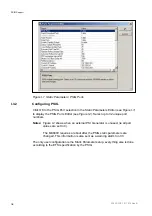
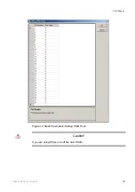
Страница 216: ...up to 32 unique port numbers Notes Figure I 2 shows when an external PSI Generator is unused ie all port values are set to 0 The MX8400 requires a reboot after the PSIG static parameters are changed T...

Страница 217: ...PSIG Support Figure I 2 Static Parameters Editing PSIG Ports Caution If you are using PSIG turn off the nCC PSI SI 2 1553 FGC 101 1014 Uen B I 5...

Страница 218: ...eing the PSI SI in the output transport stream The PSIG generator should be reporting any problems I 4 2 Error Messages All PSIG errors are defined in Section 9 9 of the ETSI specification If any of t...

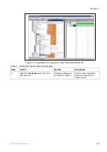
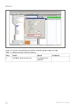
Страница 219: ...d J 7 List of Figures Figure J 1 Popup Menu For Service To Set The Session Word On J 5 Figure J 2 Location of the BISS Session Word Control Properties Advanced Tab J 6 Figure J 3 Popup Menu For Compon...

Страница 220: ...BISS Support 2 1553 FGC 101 1014 Uen B J 2 BLANK...

Страница 221: ...omponents are scrambled by a fixed Control Word CW derived from a clear Session Word SW Mode E All components are scrambled by a fixed CW derived from an encrypted session word ESW BISS Modes 0 and 1...

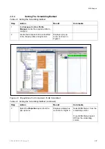
Страница 222: ...Maximum number of scrambled components per output is 256 Maximum number of session words is 512 J 3 2 Setting The Session Word Use the steps in Table J 1 to set the Session Word Table J 1 Setting the...

Страница 223: ...rd On Table J 1 Setting the Session Word continued Step Action Result Comments 3 Select the Properties option from the pop up menu Displays a dialog box as shown in Figure 2 Enter a valid 12 digit HEX...

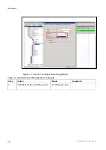
Страница 224: ...ion of the BISS Session Word Control Properties Advanced Tab Table J 1 Setting the Session Word continued Step Action Result Comments 4 Click OK to set the session word The dialog box will disappear 2...

Страница 225: ...the chosen profile and right click Displays a pop up menu as shown in Figure 3 Figure J 3 Popup Menu For Component To Be Scrambled Table J 2 Setting the Scrambling Method continued Step Action Result...

Страница 226: ...553 FGC 101 1014 Uen B J 8 Figure J 4 Control To Configure Scrambling Method Table J 2 Setting the Scrambling Method continued Step Action Result Comments 4 Click OK to set the scrambling method The d...

Отзывы: