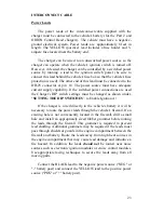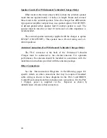
12
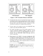
UDC Released
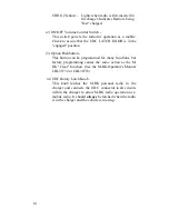
UDC Engaged
Figure 3 - UDC Connector Rotary Latch Knob
5.
If desired, the radio can now be locked into the charger to prevent
unauthorized removal. To lock the radio in the charger, insert the
key in the hole in the RELEASE BUTTON, turn in a clockwise
direction until it stops and remove the key. To unlock the radio,
insert the key and turn it in a counterclockwise direction.
6.
Turn the radio on by rotating its power on-off/VOLUME knob
clockwise out of the detent (OFF) position.
7.
The charger and radio are now set for mobile operation. Use the
charger's VOLUME CONTROL KNOB to adjust the external
speaker volume level and use the MICROPHONE's PTT button to
transmit. The red TRANSMIT INDICATOR lights when the
radio is transmitting.
8.
When removal of the M-RK is necessary, disengage the UDC
INTERFACE by pressing down on the RELEASE
BUTTON until
the ROTARY LATCH KNOB snaps to the released position. (If
the Rotary Latch Knob is locked, it must be unlocked before it will
snap release. See step 5. above.) Grip the radio on its sides and
pull it out of the charger.
NOTE
NEVER insert nor remove the radio from the charger unit by
pulling on the antenna, or using it as a handle, as this may
damage the antenna.
17
¨
Mounting Bracket and Mounting Hardware 344A4616P11
(mounting hardware includes four machine screws, four lock
washers, six self-tapping screws and one cable tie)
¨
Operator's/Installation Manual LBI-38935 (this manual)
PLANNING THE INSTALLATION
The installation of the Standard Vehicular Charger or the
Enhanced Vehicular Charger should be carefully planned, before work
actually begins.
Mechanical installation guidelines include mounting the unit:
•
in a location that is safe for the operator and any passengers
in the vehicle
•
in a location that is convenient for the operator to use
•
in a location that allows the operator to easily slip the radio
into and out of the unit
•
in a location that allows easy operator access to the external
microphone or other options that can be attached (Enhanced
Vehicular Charger unit only)
•
in a location that is protected from water damage
•
in a location that is out-of-the-way of auto mechanics
•
in a location that is out-of-the-way of any passengers
•
in a location that provides adequate clearance for attaching
cables and connectors
•
so it can be easily removed for cleaning and servicing
•
securely so that it is not likely to break loose in the event of a
collision
Содержание M-RK 344A4616P1
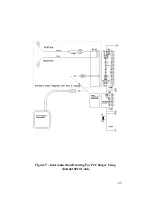
Страница 25: ...25 Figure 5 Interconnection Drawing For P2 Charger Using 344A4616P10 Cable ...
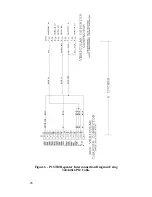
Страница 26: ...26 Figure 6 P1 STD Repeater Interconnection Diagram Using 344A4616P12 Cable ...
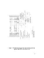
Страница 27: ...27 Figure 7 P2 Enhanced Charger Interconnection Diagram Using Optional ORION Control Head Cable ...
Страница 28: ...28 Ericsson GE Mobile Communications Inc Mountain View Road Lynchburg Virginia 24502 Printed in U S A ...


