10
11
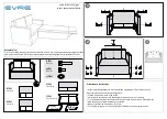
A Y-Cord is included with the base. Not available on Queen, Full or Full-Long size bases.
The Y-Cord connects the two control boxes to a single remote for the synchronization of two bases.
Locate the control box underneath the base. Plug end of
y-cord into wired remote port on the control box. Repeat for
other end of cord and second control box.
Once the remote has been connected to the control box with
the y-cord, plug bases into power outlet and test all functions.
Plug remote into Y-Cord
Unplug bases from power source.
STEP 3
STEP 2
STEP 1
STEP 4
syncing two bases (optional)
Remote
Y-Cord
Control Box
Bed A
Control Box
Bed B
You may now connect your headboard to the attachment
plates using the remaining short bolts and nuts to secure it to
the brackets. The heads of the bolts will face outward. Use a
9/16" socket and 1/2" wrench to tighten the bolts.
headboard bracket installation guide (optional)
STEP 1
STEP 2
STEP 3
a.) Align the hole in the bracket to the brass sleeve into which
the leg threads. Hold the bracket in place and screw the
leg into the base until it is snug. DO NOT OVERTIGHTEN.
Too much force may cause the leg to spin freely.
b) Align the tab with the hole in the frame (located towards
the foot of the base) and use a short bolt and nut to
secure the bracket. Make sure the bolt is tight.
Attach the plastic spacer and T-Bracket.
a.) Measure the distance between the mounting holes on the
headboard and install the spacer and attachment plate to
accommodate the headboard.
b.) To install the plastic spacer and attachment plate, you
will need (2) long bolts and (2) nuts. Place the spacer
and attachment plate in the desired location and slip the
bolts through the holes with the head of the bolt facing
outward. Position the bolts diagonally on the spacer. Use
the 9/16” socket and wrench to tighten the bolts.
Headboard Brackets are an optional accessory and are not included.
A 9/16” & 1/2” socket and crescent wrench are necessary to complete installation.


