background image


EG_GenPro400e_1103_UG_001_UK


Page 36 / 46 


Descriptions and non-contractual illustrations in this document are given as an indication only. 

ERCOGENER reserves the right to make any modifications. 

Dct_427_02


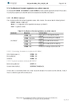
5.8  Starting with the modem 

5.8.1 

Mounting the modem 

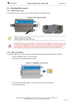
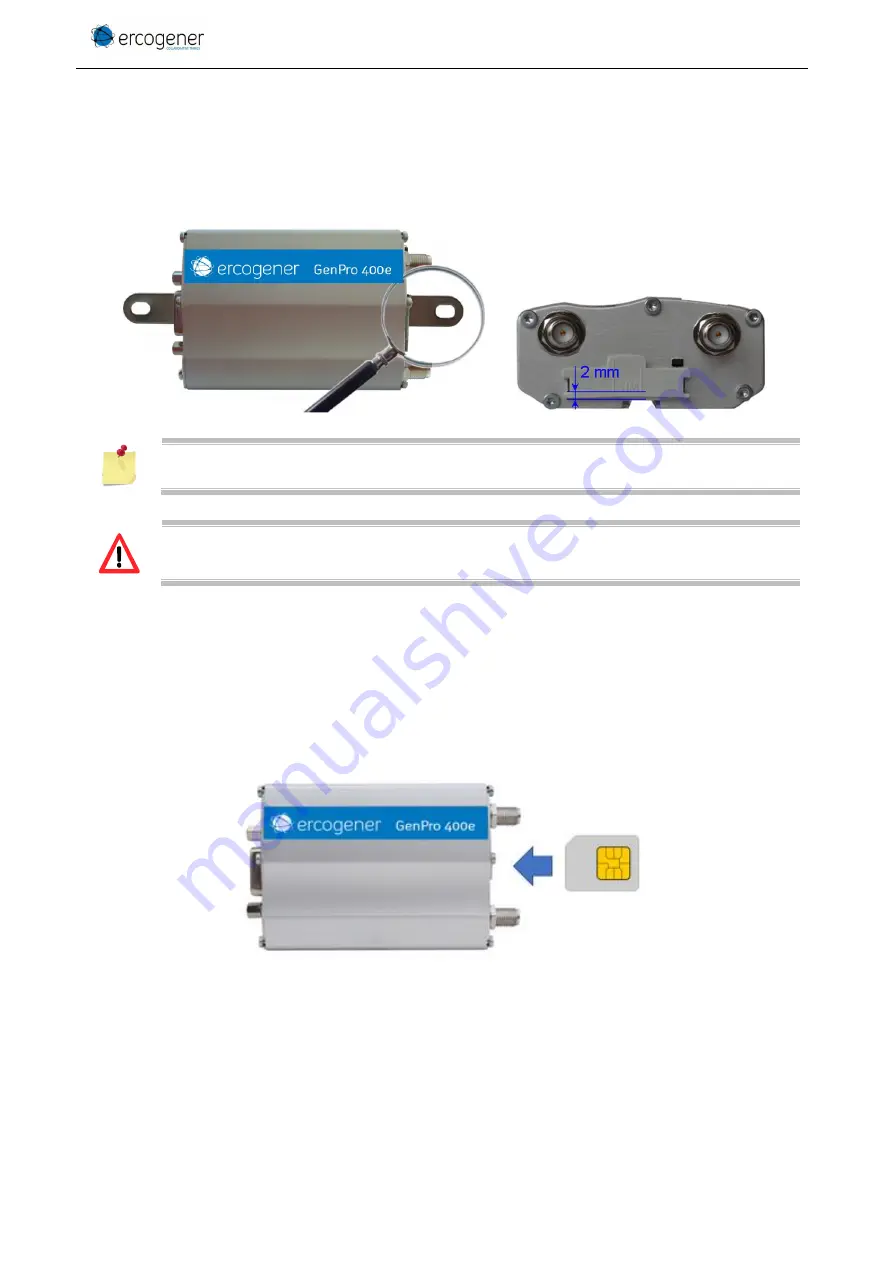
To mount the modem on a support, use the fixing brackets as described below. 


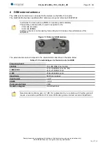
Figure 24 : Mounting the modem 


- Must be fixed on a flat surface  
- Max. height of the screw head: 2 mm 


The aluminium casing of the modem is connected to the 0V (GND) of the power supply and 
to  the  0V  of  the  RS232  serial  link.  To  avoid  any  risk  of  conduction  of  the  ground  plane  to 
other equipment, the modem must be electrically insulated from its mechanical support. 


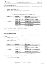
5.8.2 

SIM card installation 

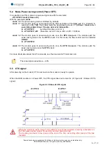
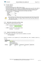
To install the SIM card, it is recommended to do the following operations with the modem turned OFF: 

-  Remove the SIM card cover on the back side. 

-  Carefully insert the SIM card into the reader. 


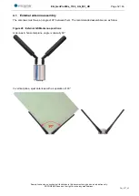
Figure 25 : Installation of the modem 


-  Push the SIM card until hearing a "click" that ensures its correct positioning. 

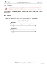
-  Put the SIM cover back. 


Содержание GenPro 400e

Страница 1: ...User Guide GenPro 400e Reference EG_GenPro400e_1103_UG_001_UK Revision 001 Id 3900 Date december 2019 http www ercogener com Dct_427_02 ...

Страница 2: ...erves the right to make any modifications Dct_427_02 Document History Rev Modifications Author Date Validation Date 000 Creation YST 04 04 2019 DJE 04 04 2019 001 Information update PGL 03 12 2019 LGO 06 12 2019 The main modifications of this document compared to the previous version are easily identifiable on a screen by the blue color of the text ...

Страница 3: ...CKAGING 11 2 3 MECHANICAL CHARACTERISTICS 12 2 3 1 Fixing brackets 12 2 4 CHARACTERISTICS AND SERVICES 13 2 4 1 Services 13 2 4 2 Interfaces 13 2 5 ENVIRONMENTAL CHARACTERISTICS 14 3 INTERFACES AND CONNECTIONS 15 3 1 FRONT SIDE 15 3 2 BACK SIDE 16 3 3 FUNCTIONAL ARCHITECTURE 16 3 3 1 General 16 3 4 POWER SUPPLY 17 3 4 1 Power supply cables 17 3 4 2 Power supply 17 3 4 3 Consumptions 18 3 4 3 1 Pow...

Страница 4: ...SIGNAL 35 5 8 STARTING WITH THE MODEM 36 5 8 1 Mounting the modem 36 5 8 2 SIM card installation 36 5 9 USE THE MODEM 37 5 9 1 Checking the communication with the modem 37 5 9 2 Using the documentation of AT command list 37 5 10 VERIFICATION OF THE PIN CODE 38 5 11 CHECKING THE LEVEL AND QUALITY OF THE RF RECEIVING SIGNAL 38 5 11 1 Response with modem attached to 2G network 39 5 11 2 Response with...

Страница 5: ...ual illustrations in this document are given as an indication only ERCOGENER reserves the right to make any modifications Dct_427_02 ANNEX 1 4 PINS MICRO FIT CABLE 2 WIRES WITHOUT FUSE 44 ANNEX 2 USB 2 0 CABLE TYPE A MALE TYP MINI B MALE 45 ANNEX 3 RF CHARACTERISTICS 45 ...

Страница 6: ...nd 5 850 MHz Band 8 900 MHz Band 3 1800 MHz Band 1 2100 MHz Band 7 2600 MHz Band 5 850 MHz Band 8 900 MHz Band 2 1900 MHz Band 1 2100 MHz GSM 850 MHz E GSM 900 MHz DCS 1800 MHz PCS 1900 MHz See also ANNEX 3 RF characteristics The protocols of IP connectivity integrated in the GenPro 400e allow the quick installation of embedded telematics solutions with strong added value This document describes t...

Страница 7: ... for the watching of physical persons where human life is engaged ercogener reserves the right to modify the functions of its products GenPro 400e without previous notice To avoid any risk of electrocution do not open the casing For any functioning the casing must be closed No internal part can be repaired by the user The GenPro 400e must be returned to the factory for any repair with RMA request ...

Страница 8: ...For more information thank you to contact your nearest legally qualified local government representative ercogener follows a method of continuous development Consequently ercogener reserves the right to change and improve any of its products described in this document without notice The contents of this document are provided as it is Except for the applicable obligatory laws no guarantee in any fo...

Страница 9: ...places where medical equipment may be used Restrictions of use of radio equipment in places where signs indicate that the use of cellular phones is prohibited or dangerous There can be a danger associated with the use of your GSM modem close to insufficiently protected medical equipment such as audio devices and pacemakers Consult the manufacturers of medical equipment to know if it is adequately ...

Страница 10: ...e this product for many years Do not expose the modem to the extreme environments to high temperature or high humidity Do not use or store the modem in dusty or dirty places it could be damaged Do not try to disassemble the modem at the risk of cancelation of the guarantee Do not expose the modem to water rain or spilled beverage it is not impermeable Avoid dropping striking or shaking the modem v...

Страница 11: ..._02 2 Description 2 1 Content The GenPro 400e is supplied with a GenPro 400e cardboard packaging a modem GenPro 400e 2 fixing brackets a power supply cable 2 wires Red Black stripped without fuse Cable USB 2 0 Type A mini B a technical sheet Instructions Sheet Figure 1 Content 2 2 Modem packaging The external dimensions of the modem packaging are Width 110 mm Height 55 mm Length 68 mm Weight 172 g...

Страница 12: ... 5 mm connectors excluded Complete dimensions 104 x 92 x 40 mm Weight 90 grams modem only 152 grams modem modem brackets cables Volume 101 5 cm Casing Aluminium profile Waterproof level IP31 The illustration below shows the dimensions of the modem including the clearances necessary for the installation of the modem Figure 2 Dimensions and clearances 2 3 1 Fixing brackets 2 brackets to fix the mode...

Страница 13: ...0 Mbit s UL 3GPP Release 9 FDD Bands 1 3 5 7 8 20 EU Asia Africa All channel bandwidths 1 4 20 MHz MIMO 2x2 UMTS DC HSPA Bands in MHz 850 900 1 900 2 100 42 Mbit s downlink 5 76 Mbit s uplink Rx diversity GSM Bands in MHz 850 900 1 800 1 900 GPRS EDGE Class 12 SMS MT MO PDU Text mode SMS over IMS and via SMS C Voice CSFB Code HR FR EFR AMR AMR WB Echo cancelation noise reduction See also ANNEX 3 R...

Страница 14: ...cations Dct_427_02 2 5 Environmental characteristics To ensure a correct operation of the Modem the specific limits described in the table below must be respected Table 5 Environmental characteristics Operating temperature range 20 C à 60 C Storage temperature range 40 C à 85 C Operating humidity without condensation HR 70 55 C Atmospheric pressure 700 hPa à 1060 hPa 400 m à 3000 m ...

Страница 15: ... No Connected 1 No Connected 1 VUSB 2 No Connected 2 Data transmission 2 Data D 3 GND 3 No Connected 3 Data D 4 VDC 4 Microphone 4 Non connecté 5 Microphone 5 GND 6 Data reception 6 Loudspeaker 7 Data set ready 7 Loudspeaker 8 Data terminal ready 8 Not connected 9 Signalization ground 9 Microphone 10 Loudspeaker 10 Microphone 11 Ready to send 12 Request to send 13 Call indicator 14 Reset 15 Loudsp...

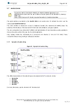
Страница 16: ... only ERCOGENER reserves the right to make any modifications Dct_427_02 3 2 Back side Figure 5 Back side Antenna connectors are female SMA type with 50Ω impedance 3 3 Functional architecture 3 3 1 General Figure 6 Functional architecture Connector SMA F MAIN GSM Antenna GSM LED SIM card cover Connector SMA F auxiliary GSM Antenna ...

Страница 17: ... used The power supply to the modem is done only via the pins 4 VDC and 3 GND 3 4 2 Power supply The modem must be powered by an external DC voltage between 7 2VDC and 32VDC The internal regulation is done by a DC DC converter and allows the supply of all necessary internal DC voltages The modem is also internally protected against voltage peaks of more than 32 VDC The following table describes th...

Страница 18: ...USB disconnected Table 11 Consumption with Power Saving mode Power Saving IMOY MAX Unit VIN 7 2 12 24 32 VDC 2G GSM GPRS 2 45 1 7 1 0 9 mA 3G UTRAN HSDPA HSUPA 4 3 2 8 1 6 1 2 mA 4G LTE 8 3 5 5 3 2 3 mA The GenPro 400e is attached to network in power saving mode with command AT UPSV 1 without data transfer and serial port RS232C and USB disconnected RS232C and USB an additional consumption can app...

Страница 19: ...ke any modifications Dct_427_02 3 4 3 1 Power supply dimensioning The below graph shows the maximum peak current The power supply must be able to supply this current during the GSM Burst Figure 7 Max consumption This consumption is not permanent It corresponds to the burst consumption during 2G GSM communications 0 500 1000 1500 2000 0 5 10 15 20 25 30 35 IMAX mA VIN V ...

Страница 20: ... 8 I DTR Data terminal ready CT106 CTS 11 O CTS Ready to send CT105 RTS 12 I RTS Request to send CT125 RI 13 O RI Call indicator GND 9 Ground Table 14 Characteristics of serial link RS232C Characteristics Symbols Conditions Min Typ Max Unité Input Voltage Range VINPUT Input Voltage Range 25 25 VDC Input Voltage Low VIL Input Voltage Low 0 6 1 1 VDC Input Voltage High VIH Input Voltage High 1 5 24 ...

Страница 21: ...cted GND 5 Ground Table 16 Characteristics of standard USB serial link Characteristics Min Typ Max Unit Current sink at VUSB_DET 30 μA High speed squelch detection threshold input differential signal amplitude 100 150 mV High speed disconnect detection threshold input differential signal amplitude 525 625 mV High speed data signaling input common mode voltage range 50 500 mV High speed idle output...

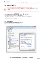
Страница 22: ... in the download area of our products To avoid provider data traffic remove the SIM card during installation 1 Download from our website ercogener com the drivers to your PC 2 Execute the download file ublox_TOBY L2xx_windows_3264__vx x x x exe 3 Follow the installation and complete the different answers 4 Once the driver installation is done turn the modem ON and connect the USB cable Wait for th...

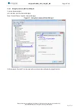
Страница 23: ...COGENER reserves the right to make any modifications Dct_427_02 3 6 4 Using the modem with the USB port To know the associated port numbers open the Device Manager Start Control Pannel System Device Manager Figure 11 Using the modem with the USB port In this example the port 21 can be used with a communication software like HyperTerminal ...

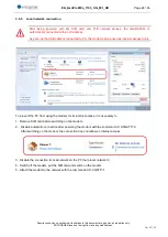
Страница 24: ... USB cable is connected to PC the modem can be used as internet access point To prevent the PC from using the modem for its internet access it is necessary to 1 Remove SIM card before switching on the modem 2 Disable automatic connection after powering the modem with the command AT UCGATT 0 After switching on the modem the connection does not allow an internet access 3 Disable the connection to lo...

Страница 25: ...and AT UEXTDCONF 0 1 The audio interface is standard to connect a telephone handset the command AT USPM allows the selection of the Handset cf the document AT Command List available on ercogener website The echo cancelation see command AT UMGC and particularities of sound reduction are also available to improve the audio quality in the case of a free hand application They already include the funct...

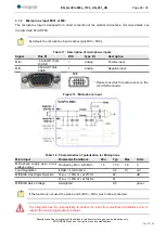
Страница 26: ...Positive input MIC 5 Sub HD 15pts 9 USB I Analog Negative input Please consult us for audio access on the mini USB connector Figure 13 Microphone input Table 18 Characteristics of polarization for Microphone Micro Input Parameters Conditions Min Typ Max Units Microphone supply open circuit voltage output Provided by MIC with MIC 1 5 1 55 1 6 V Load Regulation ILOAD 1mA to 2mA 0 2 10 mV MICBIAS Lin...

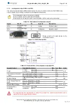
Страница 27: ...n SPK 10 Sub HD 15pts 6 USB O Analog Positive output SPK 15 Sub HD 15pts 7 USB S Analogique Negative output Please consult us for audio access on the mini USB connector Figure 14 Sortie Haut parleur Table 20 Characteristics of loudspeaker output 25 C Speaker Output Parameter Conditions Min Typ Max Units Power f 1kHz THD N 1 RL 16Ω 30 50 mW RL 32Ω 33 Total Harmonic Distortion Noise RL 32Ω POUT 25mW...

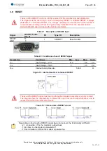
Страница 28: ...scription of RESET input Signal Sub HD 15 pins Pins N I O Type I O Description RESET GND 14 9 I SCHMITT Reset modem Table 22 Conditions of use of RESET signal Paramètres Conditions Min Typ Max Unité VIL Input Voltage Low 0 3 0 8 VDC VIH Input Voltage High 2 3 3 VDC RIPU Internal Pull Up Resistor 5 38K Ω Figure 15 Internal electrical scheme of RESET The use of the RESET signal must be done through ...

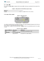
Страница 29: ...SIM card 3 V ou 1 8 V Format Standard mini SIM 3FF 25 x 15 x 0 76 mm 3 10 Leds of the modem Figure 17 Back side Leds The status of the GSM module is indicated by the status of the YELLOW GSM LED situated on the back side of the modem This is the yellow LED situated on the left The command to validate this functionality is AT UGPIOC 21 2 It is automatically saved in non volatile memory Table 24 Sta...

Страница 30: ...03_UG_001_UK Page 30 46 Descriptions and non contractual illustrations in this document are given as an indication only ERCOGENER reserves the right to make any modifications Dct_427_02 Figure 18 Chronogram of GSM Led ...

Страница 31: ... mode diversity 4G mode MIMO Auxiliary antenna is not mandatory for working but it increases the performance of the equipment Figure 19 External GSM antenna The external antenna must respond to the characteristics described in the table below Table 25 Caractéristiques de l antenne externe GSM Frequency band 850 900 780 960 MHz 2G 3G 4G 1 800 2 100 1710 1990 MHz 2G 3G 4G 2110 2170 MHz 4G 2 600 2500...

Страница 32: ... ERCOGENER reserves the right to make any modifications Dct_427_02 4 1 External antenna assembly The antennas must have an angle of 90 between them The recommanded assemblies are as follow Figure 20 External GSM antenna positions Antennas in horizontal plane angle is naturally 90 In vertical plane ajust antennas with a separation of 90 ...

Страница 33: ...und of the truck usually connected to the fuse box Most of truck circuit breakers do not cut the PLUS of the battery but cut its GROUND Figure 21 Recommended connection on the battery of a truck The scheme above shows a recommended power connection where the connection of the modem ground is not directly connected to the battery but connected after the circuit breaker on the ground of the truck or...

Страница 34: ... 615 1998 ms mode 2 The module goes to power saving mode once the RTS disappears The module quits the power saving mode once the RTS is back For this mode the flow control must be inhibited AT K0 Ex AT UPSV 2 mode 3 The module goes to power saving mode once the DTR disappears The module quits the power saving mode once the DTR is back Ex AT UPSV 3 For more information about the AT commands see the...

Страница 35: ...ons Dct_427_02 5 6 RTS Signal Using RTS flow control signal with serial link RS232C is mandatory RTS signal should not be left unconnected If RTS signal is off the modem will buffered AT commands These commands will be executed only when RTS is set again 5 7 Ri Signal The RI signal depending on its rhythm indicates either an incoming call or a SMS reception Figure 23 Status of RI signal ...

Страница 36: ...ad 2 mm The aluminium casing of the modem is connected to the 0V GND of the power supply and to the 0V of the RS232 serial link To avoid any risk of conduction of the ground plane to other equipment the modem must be electrically insulated from its mechanical support 5 8 2 SIM card installation To install the SIM card it is recommended to do the following operations with the modem turned OFF Remov...

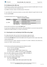
Страница 37: ... de Windows set as follows Bits prr second 115 200 bps Data Bits 8 Parity Sans Stop Bits 1 Flow control sans With an USB cable the COM port will be reserved by operating system and an Hyperterminal will not be able to open it The modem COM port must be open just after operating 20 secondes after power ON 5 9 1 Checking the communication with the modem Send the following command to identify the mod...

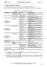
Страница 38: ...to enter the PIN code After the third attempt only a second code code PUK supplied by the operator will allow you to choose a new PIN code 5 11 Checking the Level and Quality of the RF Receiving Signal The modem will be able to make a call only if the received signal is powerful enough To verify the reception level the SIM card must be inserted and the PIN code entered The command AT CESQ allows t...

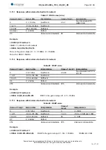
Страница 39: ... RSSI 59dBm 5 11 2 Response with modem attached to 3G network Table 28 RSCP value Value of rscp Gain in dbm Interpretation Value of ecn0 Interpretation 0 121 dbm Insufficient 0 to 49 See standard 3GPP TS 25 133 1 à 15 120 à 106 dbm Insufficient 16 à 95 105 à 26 dbm Sufficient 96 26dbm Perfect 255 Unknown not detectable 255 Unknown not detectable Example COPS 0 0 FirstOne 6 CESQ 99 99 47 44 255 255...

Страница 40: ...egistration message by default 0 Stat registration status Table 30 Verification of modem registration on cellular network Command Response Interpretation AT CREG CREG 0 0 The modem is not recognized by the network CREG 0 2 or 0 3 The modem is searching for a network operator CREG 0 1 The modem is attached to the local operator CREG 0 5 The modem is attached to the roaming operator CREG 0 4 Unknown...

Страница 41: ...work CGREG 0 5 The modem is attached to the roaming operator on GPRS network CGREG 0 4 Unknown Coverage out of 2G 3G See command AT CEREG 5 12 2 1 Chronology of answers to commands AT CGREG The same as command AT CREG 5 12 3 AT CEREG command This command verifies the status of the modem registration on 4G network The answer has the following format CEREG mode stat avec Mode configuration of the re...

Страница 42: ... CGREG 0 1 The modem is attached in GPRS to the local operator CGREG 0 5 The modem is attached in GPRS to the roaming operator CGREG 0 2 The modem is searching for a GPRS network operator CGREG 0 0 ou 0 3 The modem is not recognized by the GPRS network Verification of registration on the LTE network AT CEREG CEREG 0 1 The modem is attached in LTE to the local operator CEREG 0 5 The modem is attach...

Страница 43: ...sories recommended by ercogener for the modem GenPro 400e are described on our website in the section Products Accessories For more information please contact our sales department 7 Customer support ercogener ensures the customer support for all its modems sold You will then have access to The latest version of documents drivers Certificates To access the download area of our products documentatio...

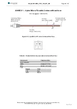
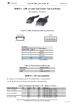
Страница 44: ...the right to make any modifications Dct_427_02 ANNEX 1 4 pins Micro Fit cable 2 wires without fuse Ref ercogener 4460302215 Figure 26 4 pin Micro FIT cable 2 wires without fuse Table 34 Characteristics of power cable 2 wires without fuse Component Characteristics 4 pin connector Cable Longueur 1 5m Wire Section 0 75 mm Fuse Signal Color VDC Red GND Blackr ...

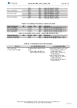
Страница 45: ...EX 3 RF characteristics RF operation is in accordance with the ETSI GSM Phase 2 recommendation The RF performance for the receiver and transmitter is described below Table 36 Sensibility of 4G network LTE Bands 1 3 5 7 8 20 Plage de fréquence Min Typique Max Unité Remarques Band 1 2100 MHz 104 5 dBm Channel bandwidth 5 MHz 98 5 dBm Channel bandwidth 20 MHz Band 3 1800 MHz 110 0 dBm Channel bandwid...

Страница 46: ...ink RF level for RMC BER 0 1 Band VIII 900 MHz 112 0 dBm Downlink RF level for RMC BER 0 1 Band II 1900 MHz 111 0 dBm Downlink RF level for RMC BER 0 1 Band I 2100 MHz 111 0 dBm Downlink RF level for RMC BER 0 1 Table 38 Sensibility of 2G network Bandes 850 900 1800 1900 Plage de fréquence Min Typique Max Unité Remarques GSM 850 E GSM 900 110 0 dBm Downlink RF level BER Class II 2 4 DCS 1800 PCS 1...

Отзывы: