background image

�������

Fig 2

Fig 3

�������

OPERATION INSTRUCTIONS

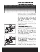
1. ADJUSTING THE CUTTING DEPTH

Move the motor base as far as possible backward. 

Set the cutting depth by turning the cutting depth 

adjustment knob. Move the motor base forwards 

and  check  if  the  pin  will  fall  in  the  notch  of  the 

adjustment knob.

The  preceding  table  shows  the  relationship  of 

the markings on the adjustment knob to cutting 

depth,  thickness  of  material  and  associated 

biscuit dowel.

2. ADJUSTING THE CUTTING ANGLE 

(see fig2)  The cutting angle can be set by unlocking 

the clamping lever and positioning the angle stop 

to the required angle.

3. ADJUSTING THE HEIGHT

(see fig3) 

The  correct  height  can  be  set  by  unlocking  the 

clamping lever for height adjustment and turning 

the  knob  for  height  adjustment  to  the  desired 

height with aid of the scale.

The  height  must  corresponds  to  half  of  the 

material  thickness  of  the  working  piece,  the 

groove  for  the  biscuit  dowel  must  always  be  in 

the middle of the working piece.

4: MOUNTING THE SAW BLADE

 (see fig 4, fig 

5)

Loosen the lock bolt with the Allen key (supplied). 

And open the base plate.

Note: You do not need to completely remove the 

bolt, just loosen sufficient for the locking washer 

to release the base plate.

Ensure the base plate does not interfere with the 

height adjustment plate.

Press the spindle lock button and turn the spindle 

until it engages in the lock.

Keep  the  spindle  lock  depressed  during  this 

Marking

0

10

20

S

D

Max.

Thickness of material

8-12mm

12-15mm

>15mm

--
--
--

Biscuit dowel

No.0

No.10

No.20

simplex

duplex

--

Cutting depth

8.0mm

10.0mm
12.3mm
13.0mm
14.7mm
18.0mm

Содержание ERB900

Страница 1: ...BISCUIT JOINTER ERB900 WARRANTY YEARS...

Страница 2: ......

Страница 3: ...routine maintenance Failure of consumable items such as batteries Accidental damage Cosmetic damage Failure to follow manufacturer s guidelines Loss of use of the goods Repairs attempted by anyone unl...

Страница 4: ...d away from heat oil sharp edges or moving parts Damaged or entangled cords increase the risk of electric shock e When operating a power tool outdoors use an extension cord suitable for outdoor use Us...

Страница 5: ...ccidentally d Store idle power tools out of the reach of children and do not allow persons unfamiliar with the power tool or these instructions to operate the power tool Power tools are dangerous in t...

Страница 6: ...re that the blade has been mounted and fastened properly Do not use reducing rings or adapters to make the blade t properly 11 Apply the machine to the workpiece only when the machine is switched on 1...

Страница 7: ...cessary for the tool to be earthed Important note Remove the main plug from socket before carrying out any adjustment or servicing Ensure your mains supply voltage is the same as your tool rating plat...

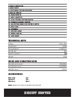
Страница 8: ...1 AUXILIARY HANDLE 2 CLAMPING LEVER FOR ANGLE ADJUSTMENT 3 CLAMPING LEVER FOR HEIGHT ADJUSTMENT 4 FENCE 5 KNOB FOR ADJUSTING HEIGHT...

Страница 9: ...ower level 102 3dB A Vibration level 2 5m s2 ACCESSORIES Dust bag 1pc Spanner 1pc Allen key 2pcs Note Blade size 100mm outer x22mm bore 6 ANGLE INDICATOR 7 BASE PLATE 8 LOCK KNOB FOR BLADE COVER 9 ON...

Страница 10: ...or height adjustment and turning the knob for height adjustment to the desired height with aid of the scale The height must corresponds to half of the material thickness of the working piece the groov...

Страница 11: ...h the slider switch forward For continuous operation push the slider switch forward and push the front down until it locates in the lock position To turn the tool off press the rear of the slider swit...

Страница 12: ...hine on Push the motor base carefully forward as far as possible Move the motor base backward and switch the machine off 10 JOINING THE WORKPIECES When the groove in both workpieces have been made the...

Страница 13: ...ckwards Set the cutting depth by turning the knob 14 the knob is positioned at the back of the pin Repeat the procedure till the cutting depth is correct ENVIRONMENTAL PROTECTION Waste electrical prod...

Страница 14: ...llows the instruction below IMPORTANT The wire in the mains lead are coloured in accordance with the following code Blue Neutral Brown Live The wire that is coloured blue must be connected to the term...

Страница 15: ...s of the following directives 89 336 EEC 93 68 EEC EMC Directive 73 23 EEC 93 68 EEC Low Voltage Directive 98 37 EC Machinery Directive Standards and technical speci cations referred to EN 60745 1 200...

Страница 16: ......

Отзывы: