PPM3 MKII Programmer - User Guide - V1.04 - 10
th
May 2008
73
4.9.2 Instructions
The instructions below detail how to set up the programmer when the Target System is independently
powered from the Target System.
Example:
•
The Target System is powered at 3.3V from an
‘Independent Power Supply’
.
•
The programmer ‘Line Driver Circuitry’ must also be powered at 3.3V using
the ‘Programmer
controlled Target Power Supply’
•
The Programmer TVCC and Target System Vcc are not physically connected
Here is how to set up the programmer:
1. Create a Programming Project which powers the programmer ‘I/O Level Converters’
•
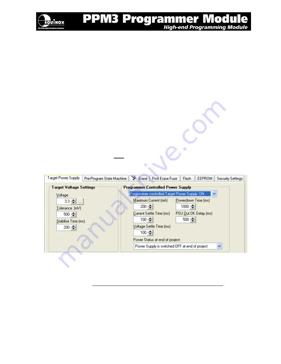
In EQTools – Project Builder – Select the
<Target Power Supply>
tab
•
Set the required
‘Target Voltage’
and tolerance eg. 3.3V +/- 500mV.
•
The
Voltage
‘Stabilise Time’
should be set to a long enough time to allow the voltage
to reach its final voltage (default: 200ms).
•
Set
the
‘Programmer controlled Power Supply’
to
‘ON’
Æ
This enables the programmer to supply power to the programmer ‘I/O Level
Converters’ only.
•
The Target System is
NOT
powered by this voltage as the
Programmer_Vcc
and
Target Vcc
are physically disconnected.
•
Leave all other settings as the default values.
2. Connect the Target System to the programmer
•
Connect the Target System to the programmer via an ISP Cable, Fast Connect connectors
or wire-wrap connectors.
•
Make
sure
that
the Programmer_Vcc is NOT connected to the Target_Vcc
. This may
involve physically cutting the Vcc signal in the ISP cable if you are using one of the ISP
headers to connect to the Target System. This is shown as a virtual link called
‘LK1’
on
the programmer schematic – see section 4.4.
•
Remove
the
‘Vcc Option Link’
on the I/O Connector Module (labelled J6 or J28).
•
Using a DVM, check that there are no shorts between the
Target_Vcc
and
Target
Ground
Содержание PPM3 MK2
Страница 1: ...User Guide...


