background image

EPSON Stylus Color 440/640/740

Revision A

Chapter 5

Adjustment

149

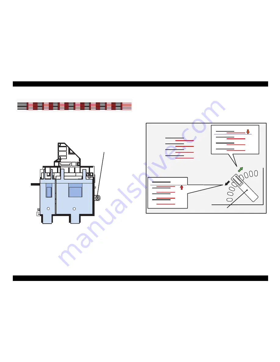
Figure 5-28. Sample of Head Angular Adjustment Pattern

5. Loosen the printhead securing screw securing the printhead on the 

carriage. (You don

'

t need to remove it completely.)

Figure 5-29. . Screw Position

NOTE: Make sure to loosen this screw. Otherwise, the printhead 

angle will no change even if the adjusting lever moves.

6. Look at the black/magenta combination in the pattern and move the 

adjusting lever to make the magenta lines stay between the black 
lines with even space. The figure below shows how the pattern 
changes as the adjusting lever moves right (rear) or left (front).

Figure 5-30. 

Lever Operation and Corresponding Change in Pattern

Head Angular Adjustment Pattern (BK-M)

Printhead securing screw

To move this up,

Correct condition = evenly spaced

move the lever to
the left (front).

move the lever to the
        right (rear). 

Adjusting Lever

To move this down,

Содержание Stylus Color 440

Страница 1: ...EPSONStylusColor440 640 740 Color ink jet printer 4009667 ...

Страница 2: ...e contents of this manual However should any errors be deteced SEIKO EPSON would greatly appreciate being informed of them The above not withstanding SEIKO EPSON CORPORATION can assume no responsibility for any errors in this manual or the consequences thereof EPSON is a registered trademark of SEIKO EPSON CORPORATION General Notice Other product names used herein are for identification purpose on...

Страница 3: ...NUAL DO NOT CONNECT THE UNIT TO A POWER SOURCE UNTIL INSTRUCTED TO DO SO WHEN THE POWER SUPPLY CABLE MUST BE CONNECTED USE EXTREME CAUTION IN WORKING ON POWER SUPPLY AND OTHER ELECTRONIC COMPONENTS WARNING 1 REPAIRS ON EPSON PRODUCT SHOULD BE PERFORMED ONLY BY AN EPSON CERTIFIED REPAIR TECHNICIAN 2 MAKE CERTAIN THAT THE SOURCE VOLTAGES IS THE SAME AS THE RATED VOLTAGE LISTED ON THE SERIAL NUMBER R...

Страница 4: ...scribes the theory of electrical and mechanical operations of the product CHAPTER 3 TROUBLESHOOTING Provides the step by step procedures for troubleshooting CHAPTER 4 DISASSEMBLY AND ASSEMBLY Describes the step by step procedures for disassembling and assembling the product CHAPTER 5 ADJUSTMENTS Provides Epson approved methods for adjustment CHAPTER 6 MAINTENANCE Provides preventive maintenance pr...

Страница 5: ...REVISION STATUS Rev Date Page s Contents A 1998 07 15 All First Release B 1998 09 30 Page 188 Pages 195 to 212 The exploded diagrams and part list for the Stylus Color 740 has been added ...

Страница 6: ... 39 C257 Main Board Stylus Color 740 40 Power Supply Board C206 PSB PSE Stylus Color 440 640 C257 PSB PSE Stylus Color 740 40 C206 PNL Board Stylus Color 440 640 41 C209 PNL Board Stylus Color 740 41 Operating Principles Overview 43 Printer Mechanism 44 Electrical Circuit Operating Principles 56 C206 PSB PSE and C257 PSB PSE Power Supply Board for Stylus Color 440 640 740 57 C206 Main B C255 Main ...

Страница 7: ... Adjustment Program 134 Maintenance Overview 154 Cleaning 154 Service Maintenance 154 Lubrication 155 Appendix Connector Summary 161 Connector Summary Stylus Color 440 640 162 Connector Summary for Stylus Color 740 166 EEPROM Address Map 169 EEPROM ADDRESS Map Stylus Color 440 640 169 EEPROM Address Map Stylus Color 740 174 Circuit Board Component Layouts 178 Exploded Diagrams 188 Part List 198 Pa...

Страница 8: ... PRODUCTDESCRIPTION ...

Страница 9: ...zles for Stylus Color 740 Built in auto sheet feeder Holds 100 cut sheets 55g m2 Holds 10 envelopes Holds 10 transparency films Holds 65 special papers High speed print 200 cps for Stylus Color 440 740 Normal 200 cps Draft 400 cps only for Stylus Color 640 By using head drive frequency 14 4KHz printing speed is twice faster than Stylus Color Compact size 429mm W x 231mm D x 155mm H for Stylus Colo...

Страница 10: ...t Paper S041026 Size A4 200 sheets Photo Quality Ink Jet Paper S041061 Size A4 100 sheets Photo Quality Ink Jet Paper S041062 Size Letter Photo Quality Ink Jet Paper S041067 Size Legal Photo Quality Glossy Paper New Release S041126 Size A4 Photo Quality Glossy Paper New Release S041124 Size Letter Photo Quality Glossy Film S041071 Size A4 Photo Quality Glossy Film S041124 Size Letter Photo Quality...

Страница 11: ... Color 740 Print direction Bi direction with logic seeking Print speed and Printable columns character pitch and print quality Refer to Table 1 2 and Table 1 3 Table 1 2 Character Mode Speed Table 1 3 Graphic Mode Speed Nozzle Configuration Refer to Figure 1 1 for Stylus Color 440 Refer to Figure 1 2 for Stylus Color 640 Refer to Figure 1 3 for Stylus Color 740 Model Name Character Pitch Printable...

Страница 12: ...2 C3 C4 Y2 Y3 Y4 C M Y 90DPI 180DPI 23 24 Y20 Y21 60 62 64 59 61 25 26 2 2578 mm 7 9022 mm 10 16 mm 2 2578 mm B1 63 C1 C19 C20 C21 M 1 M 2 M 19 M 20 M 21 M 3 M 4 Y1 Y19 4 6 29 B2 27 1 2 3 5 C13 C14 C15 C M Y 90DPI 180DPI 23 24 60 62 64 59 61 25 26 2 2578 mm 7 9022 mm 10 16 mm 2 2578 mm B1 63 C12 C30 C31 C32 4 6 29 C1 C2 C3 M13 M14 M15 M12 M30 M31 M32 M1 M2 M3 Y13 Y14 Y15 Y12 Y30 Y31 Y32 Y1 Y2 Y3 ...

Страница 13: ...Stylus Color 640 740 Paper path Cut sheet ASF Top entry Feeding speed Stylus Color 440 640 190 ms 1 3 inch 2 0 inches seconds continuous Stylus Color 740 110 ms 10 16 mm 114 3 mm second Continuous Ink supply Exclusive ink cartridge Black and CMY B2 1 C M Y B1 2 3 4 7 10 13 16 19 22 25 28 31 5 8 11 14 17 20 23 26 29 32 6 9 12 15 18 21 23 26 29 32 139 140 141 142 143 144 1 2 3 4 5 6 7 8 9 10 11 1 2 ...

Страница 14: ...bles Italictable PC437 PC437Greek PC850 PC852 PC853 PC855 PC857 PC860 PC861 PC865 PC866 ISO8859 7 ISOLatin1T Bulgaria ic PC774 Estonia ISO8859 2 PC866 LAT PC866UKR PC AR864 PC APTEC PC708 PC720 Hebrew7 1 Hebrew8 1 PC862 1 NOTE 1 is not opened These character tables can not be selected in the default setting mode Typeface Bit map LQ font EPSON Roman 10 CPI 12 CPI 15 CPI Proportional EPSON Sans Seri...

Страница 15: ...003 0 11mm 0 004 Weight 64g m2 17Ib 90g m2 24Ib Quality Exclusive paper Bond paper PPC 1 2 2 2 Transparency Glossy Paper Size A4 Width 210mm 8 3 x Length 297mm 11 7 Letter Width 216mm 8 5 x Length 279mm 11 0 Thickness 0 075mm 0 003 0 085mm 0 0033 NOTE Transparency printing is only available at normal temperature 1 2 2 3 Envelope Size No 10 Width 241mm 9 1 2 x Length 104 8mm 4 1 8 DL Width 220mm 8 ...

Страница 16: ...iption 16 1 2 2 4 Index Card Size A6 Index card Width 105mm 4 1 x Length 148mm 5 8 A5 Index card Width 148mm 5 8 x Length 210mm 8 3 5x8 Index card Width 127mm 5 0 x Length 203mm 8 0 10x8 Index card Width 127mm 5 0 x Length 203mm 8 0 Thickness Less than 0 23mm 0 0091 ...

Страница 17: ...ng Area Cut Sheet See Figure 1 4 in the right column and the tables in the following page for the printable areas for Raster Graphics mode and Character mode NOTE Character mode is only suitable for Stylus Color 740 Figure 1 4 Printable Area for Cut sheet PW RM LM BM TM PL Printable Area ...

Страница 18: ... 5 5 215 9 mm 8 5 3 mm 0 12 3 mm 0 12 3 mm 0 12 14 mm 0 54 3 mm 0 12 Exclusive 190 5 mm 7 5 254 mm 10 3 mm 0 12 3 mm 0 12 3 mm 0 12 14 mm 0 54 3 mm 0 12 Table 1 5 Character Mode only for Stylus Color 740 Paper Size PW PL LM RM TM BM min A4 210mm 8 3 297mm 11 7 3mm 0 12 3mm 0 12 3mm 0 12 14mm 0 54 3 mm 0 12 Letter 216mm 8 5 279mm 11 0 3mm 0 12 9mm 0 35 3mm 0 12 14mm 0 54 3 mm 0 12 B5 182mm 7 2 257m...

Страница 19: ... wrinkled paper this can be prevented by changing the lever position to rear position marked with in spite of paper types Table 1 7 Adjust Lever Setting NOTE Return the adjust lever to the zero position which is normal position after you finish printing on all media Leaving the lever in the plus position may cause the printed image to have gaps on other media Paper Size LM RM TM BM min 10 28 mm 1 ...

Страница 20: ...package 6 months out of package Environmental conditions Temperature Storage 20 C 40 C within a month at 40 C Packing storage 30 C 40 C within a month at 40 C Transit 30 C 60 C within 120 hours at 60 C and within a month at 40 C Humidity 5 to 85 without condensation Note Ink freezes below 3 C but it returns to normal after 3 hours at room temperature 25 C Dimension Stylus Color 440 640 19 8 mm W X...

Страница 21: ...e 6 months out of package Environmental conditions Temperature Storage 20 C 40 C within a month at 40 C Packing storage 30 C 40 C within a month at 40 C Transit 30 C 60 C within 120 hours at 60 C and within a month at 40 C Humidity 5 to 85 without condensation Note Ink freezes below 3 C but it returns to normal after 3 hours at room temperature 25 C Dimension 42 9 mm W X 52 7 mm D X 38 5 mm H Weig...

Страница 22: ...ections Non operating 2G within 2 ms X Y Z directions with shipment container Resistance to vibration Operating 0 15G Operating Non operating 0 50G Non Operating NOTE 1 During non operating make sure that the head is capped NOTE 2 During the transport make sure that the head is capped and ink cartridge is installed to the printer NOTE 3 If the head is not capped at the power off state turn the pow...

Страница 23: ... frequency range 49 5 60 5Hz Rated current 0 2 A Max 0 3A Power consumption Approx 15W ISO IEC 10561 Letter pattern Energy Star compliant Insulation Resistance 10M ohms min between AC line and chassis DC500V Dielectric strength AC1500 V rms 1 minute between AC line and chassis 1 2 7 Reliability Total print volume Stylus Color 440 10 000 pages A4 Letter Stylus Color 640 25 000 pages A4 Letter Stylu...

Страница 24: ...tylus Color 640 740 Approximately 47 dB 1 2 10 CE Marking 220 240 V version Low Voltage Directive 73 23 EEC EN60950 EMC Directive 89 336 EEC EN55022 Class B EN61000 3 2 EN61000 3 3 EN50082 1 IEC801 2 IEC801 3 IEC801 4 1 2 11 Input Data Buffer 10 K byte for Stylus Color 440 32 K byte for Stylus Color 640 64 K byte for Stylus Color 740 ...

Страница 25: ...vel in the following cases During data entry see Data transmission timing When input data buffer is full During INIT signal is at low level or during hardware initialization During printer error See ERROR signal ERROR signal is at low level when the printer is in one of the following states Printer hardware error fatal error Paper out error Paper jam error Ink out error PE signal is at high level ...

Страница 26: ...ter can again accept data 11 BUSY 29 O A high signal indicates that the printer cannot receive data 12 PE 28 O A high signal indicates paper out error 13 SLCT 28 O Always at high level when the printer is powered on 14 AFXT 30 I Not used 31 INIT 30 I The falling edge of a negative pulse or a low signal on this line causes the printer to initialize Minimum 50 us pulse is necessary 32 ERROR 29 O A l...

Страница 27: ...ransfer 04H RequestdeviceID ReturnDatausingNibbleModeRev Channel Transfer NOTE The printer sends following device ID string when it is requested Table 1 11 Details of Device ID NOTE 00H denotes a hexadecimal value of zero MDL value depends on the EEPROM setting NOTE MDL value depends on the EEPROM setting Model name can be changed by changing a certain address in the EEPROM Table 1 12 shows pin as...

Страница 28: ...y Data Bit 3 7 29 O Printer busy signal and reverse channel transfer data bit 3 or 7 12 AckData Req DataBit 2 6 28 O Acknowledge data request signal and reverse channel transfer data bit 2 or 6 13 Xflag DataBit 1 5 28 O X flag signal and reverse channel transfer data bit 1 or 5 14 HostBusy 30 I Host busy signal 31 INIT 30 I Not used 32 DataAvail DataBit 0 4 29 O Data available signal and reverse c...

Страница 29: ... Do not perform data transmission ignoring ACK or BUSY signal Perform the data transmission after confirming that ACK and BUSY signals are Low NOTE 5 It is possible to perform the printing test including interface circuit without using equipment from outside when 8 bit data signal 20 27 pin is set to appropriate word code and connect them forcefully to ACK and STRB Figure 1 9 Data Transmission Tim...

Страница 30: ...lized to the idle state scanning which interface receives data when it is powered on Then the interface that receives data first is selected When the host stops data transfer and the printer is in the stand by state for the seconds the printer is returned to the idle state As long as the host sends data or the printer interface is busy state the selected interface is let as it is Following explain...

Страница 31: ...us Device Class Definition for Printing Device Version 1 0 Bit Rate 12 M bps Data Encoding NRZI Connector USB Series B Recommended Cable Length 2 meters Table 1 18 Pin Assignment Figure 1 10 USB Pin Assignment Pin No Signal Name I O Description 1 SCLK O Synchronous clock signal 2 CTS I Clear To Send 3 TXD O Transmit Data 4 SG I Signal Ground 5 RXD I Receive Data 6 TXD O Balanced Transmit Data 7 DT...

Страница 32: ...1 11 Control Panel Over Viewing 1 4 1 Indicators LEDs 1 Power Lights when the operate switch is ON and AC power is supplied 2 Paper out Lights during the paper out condition and blinks during the paper jam condition 3 Ink Out Black Lights during no Black ink condition and blinks during the Black ink low condition 4 Ink Out Color Lights during no Color ink condition and blinks during the Color ink ...

Страница 33: ... Starts the status print 1 Cleaning Stylus Color 440 640 Changes the code page 2 Stylus Color 740 Enters the Default setting mode 3 Load Eject Cleaning Enters the EEPROM Reset mode The Load Eject LED blinks for a few seconds Used only for resetting the maintenance error 4 Switch Function Cleaning Resets the EEPROM 5 1 While the Load Eject LED is blinking for about 2 seconds press down the Cleaning...

Страница 34: ... ways Table 1 22 Printer Condition and LED Status Printer Status Indicators Priority Power Ink Out Black Ink Out CMY Paper Out Power on condition 9 Ink Sequence mode On 6 I C replacement mode Blink 5 Data processing Blink 8 Paper out Blink On 4 Paper jam Off Off Blink 3 No I C Ink out bk On 7 Ink level low bk Blink 7 No I C Ink out CMY On 7 Ink level low CMY Blink 7 Enters the EEPROM Reset ON for ...

Страница 35: ...ated during the production process However this ability for absorption can last only about one hour after the cartridge is installed Step 2 Even after the bubble absorbing ability described above stops there is problem about entering bubbles as long as the ink cartridge is installed in the printer However if the ink cartridge which does not have absorbing ability any more is once removed from the ...

Страница 36: ...inter must be something wrong Same reason as above 1 5 5 Maintenance Request When the total quantity of ink wasted through the cleanings and flushing reaches to the limit printer indicates this error and stops The absorber in the printer enclosure is needed to be replaced with new one by a service person The ink quantity that is absorbed by the absorber waste ink pad is monitored by the software c...

Страница 37: ...e pulse of parallel interface When printer is initialized following action is performed a Cap the printer head b Eject a paper c Clears input data buffer d Clears print buffer e Sets default values 3 Software initialization The ESC command also initialize the printer When printer is initialized following action is performed a Clears print buffer b Sets default values 1 7 Initialization Settings St...

Страница 38: ... C206 PSB PSE Board Stylus Color 640 C206 PSB PSE Board Stylus Color 740 C257 PSB PSE Board 5 Control Panel Board Stylus Color 440 C206 PNL Board Stylus Color 640 C206 PNL Board Stylus Color 740 C209 PNL Board 1 8 1 Printer Mechanism Like the previous printer mechanism such as for Stylus Color 400 600 and Stylus Photo one of the major characteristics of Stylus Color 440 640 740 is that the printer...

Страница 39: ...s Color 640 C256 Main board controls Stylus Color 640 and consists of following major electric elements Figure 1 13 C256 Main Board Major Electric Elements C N 1 B a t t 1 I C 7 H e a d C N 6 C N 7 I C 4 4 M D R A M I C 1 C P U I C 1 4 P F I C 1 5 C R I C 3 P R O M I C 2 A s i c C N 1 0 Q 7 Q 9 H e a d C N 8 E E P R O M I C 1 1 C N 3 C N 5 C N 4 C N 1 1 I C 1 4 P F I C 2 A s i c C N 1 C N 2 B a t ...

Страница 40: ...sible to keep supplying electricity to the C206main B C255 C256 C257 main control board for 30 seconds even after the power switch is turned off Using this time difference even when mis operation is done by the user such as turning off the power during the middle of printing work it prevents thickened ink from attaching around the nozzle plate by transferring the head to cap position Figure 1 15 C...

Страница 41: ...t bottom of the front printer and consists of 3 switches 4 LEDs and 1 connector Figure 1 16 C206 PNL Board 1 8 7 C209 PNL Board Stylus Color 740 Panel board C209 PNL board is located in the panel case where is in the right bottom of the front printer and consists of 3 switches 4 LEDs and 1 connector Figure 1 17 C209 PNL Board SW0 SW2 SW1 LED4 LED0 LED1 LED2 CN1 SW0 SW2 SW1 LED4 LED0 LED1 LED2 ...

Страница 42: ... OPERATINGPRINCIPLES ...

Страница 43: ...c circuit board Electronic Boards for Stylus Color 440 are Main C206 Main B C255 Main Board Power Supply C206 PSB PSE Board Panel C206 PNL Board Electronic Boards for Stylus Color 640 are Main C256 Main Board Power Supply C206 PSB PSE Board Panel C206 PNL Board Electronic Boards for Stylus Color 740 are Main C257 Main Board Power Supply C257 PSB PSE Board Panel C209 PNL Board ...

Страница 44: ... Nozzle 64 nozzles 90 dpi x 2 rows in staggered CMY Nozzle 21 nozzles colors 90 dpi x 1 row Stylus Color 640 Black Nozzle 64 nozzles 90 dpi x 2 rows in staggered CMY Nozzle 32 nozzles colors 90 dpi x 1 row Stylus Color 740 Black Nozzle 144 nozzles 120 dpi x 3 rows in staggered CMY Nozzle 48 nozzles colors 120 dpi x 1 row Among these printers the Stylus Color 640 and 740 can print 1440 H x 720 V re...

Страница 45: ...nal from the PSB PSE board is sent through the driver board on the print head unit and to the PZT Then the PZT pushes the top cavity which has ink stored and make the ink discharge from each nozzle located on the nozzle plate Cavity Set Ink which is absorbed from ink cartridge go through the filter and will be stored temporarily in this tank which is called cavity until PZT is driven Nozzle Plate ...

Страница 46: ...ure 2 3 2 Ejecting State When the print signal is output from the C206 main B C255 C256 C257 main board IC IR2C72C Nozzle Selector located on the Print head unit latches the data once by 1 byte unit Appropriate PZT latched by nozzle selector is pushed into the cavity by applying common voltage from the main board By this operation ink that is stored in the cavity pops out from nozzles Refer to fig...

Страница 47: ...h Modes Stylus Color 440 640 Table 2 3 Motor Control at Each Modes Stylus Color 740 Figure 2 5 CR PF Motor Internal Circuit Diagram Items Description Motor type 4 Phase 200 pole Stepping motor Drive voltage Range 42VDC 5 Internal coil resistance 7 8 Ohms 10 per phase under 25 C environment Driving Speed frequency Range csp Hz 5 60 340 4080 Control method Bi Pola Drive Printing mode Drive Speed CPS...

Страница 48: ...long time ink on the print head surface gradually becomes thick As a result the nozzle will be unable to discharge ink To make matters worse the holes crater of nozzle may be completely clogged by the thick ink and it may not be able to return to the normal condition just by cleaning operation In order to prevent this printer goes to carriage lock state at the following conditions See the followin...

Страница 49: ... a motive power motor as a motive power of the paper mechanism and driving is done at 2 2 1 2 phase drive method for Stylus Color 440 640 and at 2W1 2 W1 2 1 2 and 2 2 phase drive method for Stylus Color 740 This motor is not only used as a power source for paper feed mechanism but also used as power source of pump mechanism which is necessary for print head cleaning By using this pulse motor it b...

Страница 50: ...n of 1 in the figure above Step 2 When the CAM covers the notch by the return lever that position is considered as home position being monitored by ASF sensor Step 3 When the CAM rotates toward 1 in the figure above the return lever is pushed by the notch of CAM and falls towards 2 At this time the return lever moves to direction 3 by this motion and push down the pad which is waiting in the below...

Страница 51: ...oller support drops the paper in the eject tray The eject roller is driven with an eject paper notched roller as pair where is located on the paper eject roller Paper eject notched roller solves the deflection of paper that is in the between platen eject notched roller and paper eject roller and always keep a certain space between print head and paper surface For an unique point the securing angle...

Страница 52: ... mechanism and paper feed mechanism it is one of the major characteristics that pump and platen are always at work whenever the PF motor is driven The figure below shows head positions when the ink system and various ink sequence are performed Figure 2 10 Ink System Mechanism Figure 2 11 Major Ink Sequence Position on Carriage Working Area PF Roller Drive Gear Eject Roller Drive Gear Eject Roller ...

Страница 53: ...is not done Figure 5 2 shows process of conveying motive power to the pump drive roller See Figure 1 12 The process of conveying the motive power to the paper eject roller by rotating the pinion of PF motor is descried in figure 2 10 This motive power is conveyed to the Gear C through the Gear B In the figure above although the lever in order to drive Gear C carriage lock head cleaner mechanism is...

Страница 54: ...In case of printing and flashing drive ink is popped out by the PZT in the print head but in case of absorptive operation such as cleaning and initial ink charge ink absorption is performed only by the pump drive without PZT drive after the head surface is adhered to the cap The next page explains cap mechanism and relation between printer operation and cap Figure 2 13 Pump Roller Rotation and it ...

Страница 55: ... the waste ink pad If the carriage is out of HP in this case in the printable area or paper feed position the valves on the cap mechanism stays in the position A in the figure above and are always closed In this condition the carriage collides with flag actual ink absorption and slight ink absorption are performed Also by moving the carriage to further right side and colliding the flag for opening...

Страница 56: ...ard Panel C206 PNL Board Electronic Boards for Stylus Color 740 are Main C257 Main Main Board Power Supply C257 PSB PSE Board Panel C209 PNL Board Refer to Figure 2 15 for the major connection of the 3 boards and their roles Figure 2 15 Electric Circuit of Stylus Color 440 640 740 PF MOTOR Pump Motor CR Motor C206 PSB PSE Board C257 PSB PSE Board 5 V DC AC Input INK END counter and P off time coun...

Страница 57: ...ity of clogging ink nozzle will be decreased 2 If the switch is turned off when the papers in the printer are still being carried except for the papers in the hopper the same operation mentioned above is performed and the driving power is turned off after the paper is completely ejected Table 2 8 Application of DC Voltage Figure 2 16 shows block diagram of C206 PSB PSE board The process from the i...

Страница 58: ...DC as power supply IC51 pressures down the 42VDC and generates precise 5VDC by chopping off the output forming the standard santooth wave form by the outer RC integration circuit The C206 PSB PSE board has various control circuits to stop output if malfunction on the power supply board on the main board or on the duty of printer mechanism happen Following explains each control and protection circu...

Страница 59: ...ing on PSC signal is input to the power supply board from the C206 Main B C255 C256 C257 Main board This signal turns Q84 on and it becomes possible to discharge energy between 8 9 of T1 At this time even if the power is turned off the electrolytic capacitor keeps Q84 on for a while By this electrolytic capacitor output is hold at least 30 seconds even after the power is turned off This time helps...

Страница 60: ... drive of CR PF Pump motor and printing head is performed Following figure shows the circuit diagram for Stylus Color 440 Figure 2 17 C206 Main B C255 Main Board Block for Stylus Color 440 TPM95C061 IC1 P ROM IC3 Address Data Address Data Reset IC IC9 CR1 Timer Counter IC5 Batt1 EEPROM IC11 CN1 Parallel Common Driver IC6 Q7 Q9 Head CN8 HD FFC Motor Driver IC14 Motor Driver IC15 PF Motor CR Motor C...

Страница 61: ... red to the RAM when the power is turned on Sensor Data The sensor detects information at the various conditions which is necessary for the printer operation The gate array recognizes signals and changes over to the next control Timer Data The timer IC that uses lithium battery as power source monitors how long the power is off When the power is turned on it is changed to appropriate cleaning leve...

Страница 62: ...or and printing head is performed Following figure shows the circuit diagram for Stylus Color 640 Figure 2 18 C256 Main Board Block for Stylus Color 640 TPM95C061 IC1 Address Data Address Data Reset IC IC9 CR1 Timer Counter IC10 Batt1 EEPROM IC11 CN1 Parallel Common Driver IC7 Q7 Q9 Head CN8 HD FFC Motor Driver IC14 Motor Driver IC15 PF Motor CR Motor CN6 CN7 C206 PNL CN3 CN11 ASF Sensor CN5 HP Se...

Страница 63: ...ed on Sensor Data The sensor detects information at the various conditions which is necessary for the printer operation The gate array recognizes signals and changes over to the next control Timer Data The timer IC that uses lithium battery as power source monitors how long the power is off When the power is turned on it is changed to appropriate cleaning level according to the time that the power...

Страница 64: ...head is performed Following figure shows the circuit diagram for Stylus Color 740 Figure 2 19 C257 Main Board Block for Stylus Color 740 Address Data Reset IC IC9 CR1 Timer Counter IC8 Batt1 EEPROM IC7 CN1 Parallel Q2 Q3 Head CN9 HD FFC PF Motor CR Motor CN7 C209 PNL CN11 CN6 ASFSensor CN4 HPSensor CN5 PESensor Transceiver IC10 CN2 Serial Motor Driver IC13 Common Driver IC14 CN8 Motor Driver IC12 ...

Страница 65: ...arious conditions which is necessary for the printer operation The gate array recognizes signals and changes over to the next control Timer Data The timer IC that uses lithium battery as power source monitors how long the power is off When the power is turned on it is changed to appropriate cleaning level according to the time that the power is off Serial I F Control The gate array receives serial...

Страница 66: ... reset IC IC9 monitors level of power voltage at the over loading or malfunction on the circuit and manages the printer to operate normally keeping the damage to the printer minimum during the abnormal situations On the C206 main B and C255 main board Figure 2 20 Reset Circuit for Stylus Color 440 PST592D IC8 Vcc Vout NRES GND 5V C47 R138 5V R1 RESET TMP95C061 IC1 P85 E05B44 IC2 RESET 174 30 16 1 ...

Страница 67: ... IC9 monitors level of power voltage at the over loading or malfunction on the circuit and manages the printer to operate normally keeping the damage to the printer minimum during the abnormal situations On the C256 main board Figure 2 21 Reset Circuit for Stylus Color 640 PST592D IC8 Vcc Vout NRES GND 5V C47 R138 5V R1 RESET TMP95C061 IC1 P85 E05B43 IC2 RESET 174 30 16 1 2 3 4 M62030 IC9 VCC 2 4 ...

Страница 68: ...r when the power is turned on and causes the paper to be picked up by the pick up roller from the normal initial condition Refer to section 2 1 1 3 for detail PE Sensor Photo A PE sensor determines if there is paper in the printer Based on the signal form this sensor a particular paper edge treatment such as Micro weave printing is performed HP Sensor Photo A HP sensor detects the carriage home po...

Страница 69: ...s omitted here Figure 2 23 Figure 5 23 Sensor Circuit for Stylus Color 440 Figure 2 24 Figure 5 24 Sensor Circuit for Stylus Color 640 Figure 2 25 Sensor Circuit for Stylus Color 740 5V 8 6 5 AT93C46 IC11 Vcc GND ORG E05B44 IC2 127 128 126 125 1 2 3 4 CS SK DI DO ECS ECK ECO ECI IC 2 E05B43 5V 5V CN11 CN5 CN4 ASF HP PE PE GND PEV HP GND HPV ASF GND ASFV 5V 5V 5V 5V 5V 5V 5V 206 SW4 204 SW5 202 SW6...

Страница 70: ...is connected to the Gate array by 4 lines and performs following functions The figure below shows EEPROM control circuit CS Chip selection signal CK Data synchronism clock pulse DI Data writing line serial data at power off DO Data reading line serial data at power on Figure 2 26 EEPROM Control Circuit for Stylus Color 440 Figure 2 27 EEPROM Control Circuit Stylus Color 640 Figure 2 28 EEPROM Cont...

Страница 71: ...d into the pulse form in the Timer IC When the printer is turned on the Timer IC outputs power off time as serial data to the gate array Once the printer is turned off 3VDC of BAT1 lithium battery is supplied as power source for the Timer IC through D7 Since 5V at the power on is higher than 3V of the lithium battery the power is not being consumed from the lithium battery Figure 2 29 Timer Contro...

Страница 72: ...tylus Color 440 640 740 does not have Micro dot control as dot shooting control but there are two types Normal dot and Normal dot 2dot Normal dot 2dot was called Dual Firing in the Stylus Color IIs 820 These setting change are controlled automatically by setting of the printer driver that is determined by the user The followings are required conditions to perform the normal dot 2 dot At the OHP No...

Страница 73: ... VHV 5 GND GND GND GND GND GND VDD 15 14 12 10 8 6 4 COM COM COM 19 21 20 GND2 GND2 GND2 16 18 17 E05B44 IC2 VHCTL 2 4 6 199 CCO LAT SI1 SI2 CLK NCHG BCO THM 1 2 5 9 7 11 3 13 200 198 SW7 SW8 90 LP 99 100 BIEN BHSO YCMHSO 97 96 YCMIEN ICLK BCHCLK NCHG 93 92 89 TMP95C061 IC1 AN0 20 CN8 CHG KC1 ND1 ND2 MD1 MD2 Data CLK STB CLR VRF VK CHG KC1 ND1 ND2 MD1 MD2 Data CLK STB CLR VRF VK VHCTL Vcc ...

Страница 74: ...VHV 5 GND GND GND GND GND GND VDD 15 14 12 10 8 6 4 COM COM COM 19 21 20 GND2 GND2 GND2 16 18 17 E05B43 IC2 VHCTL 2 4 6 199 CCO LAT SI1 SI3 CLK NCHG BCO THM 1 2 5 11 7 13 3 15 201 199 SW7 SW8 92 LP HSO3 101 ICLK HCLK NCHG 94 95 91 TMP95C061 IC1 P84 15 CN8 CHG KC1 ND1 ND2 MD1 MD2 Data CLK STB CLR VRF VK CHG KC1 ND1 ND2 MD1 MD2 Data CLK STB CLR VRF VK VHCTL Vcc SI2 9 HSO2 99 HSO1 97 HSOIEN 96 ...

Страница 75: ...print head to carry out printing it is necessary to transmit the printing data to the appropriate nozzles which becomes direct signals to drive PZT This data transmission is performed by the serial method however the data output for each black and CMY head is transmitted by the parallel method CXA20996 IC14 VCC45 Vcc45_2 NPNB FB PNPB VOUTGND F1 E05B588 IC2 VHCTL 22 20 CCO LAT CLK BCO THM 1 2 5 14 ...

Страница 76: ...s input However firmware does not support Micro step in the Stylus Color 440 640 740 The figures below show connection diagram of PF Pump motor drive circuit Figure 2 35 PF Pump Motor Drive Circuit for Stylus Color 440 Figure 2 36 PF Pump Motor Drive Circuit for Stylus Color 640 E05B44 IC2 PFAPH PFA1 PFA0 PFBPH PFB2 PFB0 PFV0 PFV1 PFV2 PFV3 59 58 57 46 47 48 49 LB1B45 IC15 PH1 I11 25 23 I01 22 50 ...

Страница 77: ... Stylus Color 740 5 M6252 IC16 7 6 5 C90A05 IC1 112 DA1 D0 D1 D2 PHASE REF PFD A3956 IC13 OUTA OUTB VBB VCC Current Detection D0 D1 D2 PHASE REF PFD A3956 IC13 OUTA OUTB VBB VCC 4 5 6 7 E05B588 IC2 PFIB0 PFIB1 PFIB2 PFPHAB PFIA0 PFIA1 PFIA2 PFPHAA 8 9 10 11 14 9 8 7 2 1 14 9 8 7 2 1 10 15 Rotor A A B B 1 3 2 4 CN8 10 15 ...

Страница 78: ...Bi pola drive PWM current control type is performed making it possible to provide stable current to each phase of motor The figures below show carriage motor drive circuit Figure 2 38 Carriage Motor Drive Circuit for Stylus Color 440 E05B44 IC2 PFAPH CRA1 CRA0 CRBPH CRB1 CRB0 CRV0 CRV1 CRV2 CRV3 77 76 75 46 47 48 49 LB1B45 IC14 PH1 I11 25 23 I01 22 74 PH2 18 73 I12 20 72 I02 21 Vref1 Vref2 26 17 5...

Страница 79: ...rcuit for Stylus Color 640 E05B43 IC2 CRA0 CRA1 CRA0 CRB1 CRAPH CRBPH MTBV0 MTBV1 MTBV2 MTBV3 MTBV4 75 76 75 60 61 62 63 73 77 74 Rotor A A B B 1 3 2 4 CN5 UDN2917 IC15 I10 I11 2 1 I20 23 I21 24 PH1 43 PH2 26 Vref1 Vref2 44 25 Out1A Out1B Out2A Out2B 6 3 18 21 64 5 65 66 67 70 71 5 MTAV0 MABV1 MTAV2 MTAV3 MTAV4 ...

Страница 80: ...2 3 C90A05 IC1 111 DA0 Current Detection E05B588 IC2 Rotor A A B B 1 3 2 4 CN7 CRENBA CRENBB CRPHAA CRPHAB 192 201 191 202 CRIA0 CRIA1 CRIA2 CRIA3 CRIB0 CRIB1 CRIB2 CRIB3 IA1 IA2 IA3 IA4 IB1 IB2 IB3 IB4 PHASE1 PHASE2 ENBL1 ENBL2 Vref1 Vref2 LB1847 IC11 17 2 13 26 16 27 25 24 23 22 18 19 20 21 193 194 195 196 200 199 198 197 OUTA OUTA OUTB OUTB 7 6 9 8 ...

Страница 81: ... TROUBLESHOOTING ...

Страница 82: ... Measurement Procedure Main board refers to the following Stylus Color 440 C206Main B C255Main Stylus Color 640 C256Main Stylus Color 740 C257Main See the following page for Table 3 2 Sensor Check and Table 3 3 Printer Condition and Panel Status START END Unit Level Troubleshooting Unit Repair PSB PSE Unit Repair Main board Disassemble and Adjustment Unit Repair Printer Mechanism Motor Name Locati...

Страница 83: ...home position ASF Phase Sensor Stylus Color 440 640 CN11 Pins 1 2 Open less than 0 7 V Home position Stylus Color 740 CN6 Pins 1 2 Close more than 2 4 V Out of home position Black Cartridge Sensor Stylus Color 440 640 CN8 Pins 1 18 On 0V Black cartridge out Stylus Color 740 CN9 Pins 1 19 Off more than 2 4 V Black cartridge installed Color Cartridge Sensor Stylus Color 440 640 CN8 Pins 2 18 On 0V C...

Страница 84: ... paper then press the load eject button No Ink cartridge or Ink end black On Install a new black ink cartridge by pressing the load eject button for 3 seconds No Ink cartridge or Ink end color On Install a new color ink cartridge by pressing the load eject button for 3 seconds Maintenance request Blink Blink Blink Blink Change the waste ink drain tank and reset the EEPROM Fatal error Blink On On B...

Страница 85: ...ndication Flowchart 2 Failure occurs during printing Printing is not performed Abnormal printing missing dot etc Print quality is poor Flowchart 3 Printer does not feed paper correctly No paper is fed Paper feed is irregular Paper jam occurs Flowchart 4 Control panel operation is abnormal No response to button access Flowchart 5 Is AC power voltage normal YES Is the fuse F1 of power supply Is the ...

Страница 86: ...Does the carriage move smoothly Yes Check CR motor Replace the main board if there is no problem Is the problem solved Refer to Section 3 4 Repair of the printer mechanism END NO Yes NO Yes NO START Is printing carried out O K Is print quality normal Is the problem solved Perform printing adjustment Refer to Chapter5 Replace the ink cartridge with a new one and perform self test Is the problem sol...

Страница 87: ...he paper path if there is any Clean the roller of paper path Is the Is the PF motor running Refer to Section 3 4 Repair of the printer mechanism END Check the PF motor If there is no problem replace the main board END NO YES NO YES YES NO Set the paper correctly NO problem solved START Is the control panel connected correctly Connect the control panel correctly Is the problem solved Replace the co...

Страница 88: ...r is as follows Stylus Color 440 C206 PSB PSE Stylus Color 640 C206 PSB PSE Stylus Color 740 C257 PSB PSE This section describes the problems related to the power supply board The table below provides various symptoms likely causes and checkpoints The checkpoints refer to waveforms resistance and other values to check to evaluate the operation of each component ...

Страница 89: ... operate at all 42V line is dead F1 is open Check F1 by using a tester Replace F1 Transformer coils are open Check the waveform at the drain of Q1 Replace T1 Switching FET Q1 is dead Check drain side Replace Q1 Feed back transistor Q2 Q3 are dead Check collector side Replace Q2 or Q3 42 V line is abnormal Check the following parts ZD87 ZD83 ZD51 ZD81 ZD86 PC1 Replace suitable parts ...

Страница 90: ...ylus Color 740 Stylus Color 440 640 Check the oscillation Pin 5 waveform of IC51 Pin 5 Check the switching Pin 7 waveform of IC51 Pin 7 Replace IC51 IC51 L4962E FA3635P is dead Note L4962 is used for Stylus Color 440 640 FA3635P is used for Stylus Color 740 Stylus Color 740 Check the switching Pin 8 waveform of IC51 Pin 8 Replace IC51 Table 3 5 Repair of the C206 C257 PSB PSE Board Symptom Conditi...

Страница 91: ... follows Stylus Color 440 C206MAIN B C255MAIN Stylus Color 640 C256MAIN Stylus Color 740 C257MAIN This section describes the problems related to the main controller board The table below provides various symptoms likely causes and checkpoints The check points refer to waveforms resistance and other values to check to evaluate the operation of each component ...

Страница 92: ... Pin 7 Replace IC8 Control ROM D RAM and Mask ROM are not selected correctly or it s dead Continues to the next page Stylus Color 440 If you can not find the waveform at 88 pin of IC1 the IC1 is dead and if you can not find it at 20 pin of IC3 or 26 pin of IC4 the IC3 or IC4 is dead Stylus Color 440 Replace IC1 IC3 or IC4 Stylus Color 640 If you can not find the waveform at 97 pin of IC1 the IC1 i...

Страница 93: ...IC5 Replace IC6 Stylus Color 440 CRU2 is dead Stylus Color 640 CR2 is dead Stylus Color 740 CR1 or IC2 is dead Stylus Color 440 640 Check the waveform at 27 28 pin of IC1 Stylus Color 740 Check the waveform at 118 or 119 pin of IC2 And check the output waveform at 91 pin of IC2 Stylus Color 440 640 Replace CRU2 or CR2 Stylus Color 740 Replace CR1 or IC2 The carriage does not operate normally Conti...

Страница 94: ... Printing is not execute Trapezoidal waveform does not output Stylus Color 440 Check the trapezoidal waveform at 3 pin of Q7 or Q9 on C206Main B C255 main board Stylus Color 640 Check the trapezoidal waveform at 3 pin of Q7 or Q9 on C256 Main board Stylus Color 740 Check the trapezoidal waveform at 3 pin of Q2 or Q3 on C257 Main board Stylus Color 440 Replace IC6 Q7 or Q9 Stylus Color 640 Replace ...

Страница 95: ... the waveform at Pin 7 of IC12 and IC13 Replace IC2 Stylus Color 440 640 IC15 is dead Stylus Color 740 IC12 or IC13 is dead Stylus Color 440 Check the output waveform of at 6 9 pin of IC15 Stylus Color 640 Check the output waveform of at 3 6 18 21pin of IC15 Stylus Color 740 Check the output waveform of at 10 15 pin of IC12 and IC13 Stylus Color 440 640 Replace IC15 Stylus Color 740 Replace IC12 I...

Страница 96: ...heck if the tube is out of the cap visually Connect the tube properly Pump bulb is not closed at absorption Check the bulb operation visually Replace the cap mechanism Abnormal carriage operation Abnormal carriage operation at power on Foreign substance in the CR drive gear Check visually if there is any substances or not Remove any foreign substances CR motor is defective Check the inner coil res...

Страница 97: ...tion several times and check printing If condition does not improve even after the cleaning replace the head I C is defective Install the new I C and perform self test Replace I C Black specks or dots The head FFC is out of connection Check if the head FFC on the board or carriage is connected surely Connect the FFC properly The head unit is detective Check connection with the head FFC Replace the...

Страница 98: ...ce the PF roller if it does not recover Printer stops during initialization Fatal error appears ASF sensor is defective Check the signal level of the ASF sensor Refer to Table 5 2 Replace ASF sensor PE sensor is defective Check the signal level of the PE sensor Refer to Table 5 2 Replace PE sensor HP sensor is defective Check the signal level of the HP sensor Refer to Table 5 2 Head FFC is disconn...

Страница 99: ... DISASSEMBLYANDASSEMBLY ...

Страница 100: ...eye with fresh water and see a doctor immediately If ink comes into contact with your skin wash it off with soap and water If irritation occurs contact a physician A lithium battery is installed on the main board of this printer Be sure to observe the following instructions when serving the battery Keep the battery away from any metal or other batteries so that electrodes of the opposite polarity ...

Страница 101: ...bling assembling or adjusting the printer Apply lubricants and adhesives as specified See Chapter 6 for details Make the specified adjustments when you disassemble the printer See Chapter 4 for details When assembling if an ink cartridge is removed and needs to be installed again be sure to install a new ink cartridge because of the following reasons Once the ink cartridge mounted on the printer i...

Страница 102: ...fied types of screws are used at proper locations referring to the table below Note that the screw numbers described in the manual correspond to the numbers in the table Table 4 2 Screw Characteristic No Body Name Size 1 Bind S tight M3X6 2 Bind S tight M3X10 3 Bind P tight CBP tight M3X6 4 Bind P tight CBP tight M3X10 5 Bind P tight CBP tight M3X8 6 Pan head CP M3X4 7 Bind S tight Sems R2 CBS Sem...

Страница 103: ...over heating Checked Not necessary Paper feeding mechanism Is paper fed smoothly Checked Not necessary Does paper get jammed Checked Not necessary Does paper get skew during paper feeding Checked Not necessary Are papers multi fed Checked Not necessary Does the PF motor get overheated Checked Not necessary Abnormal noise during paper feeding Checked Not necessary Is the paper path clear of all obs...

Страница 104: ...inter Mechanism 3 2 4 Refer to Remove the Print Unit 3 2 4 1 Remove the Absorber tray Assembly A 3 2 4 2 Remove the Pump Assembly Cap Assembly 3 2 4 3 Remove the CR Motor Assembly 3 2 4 4 Remove the PF Motor Assembly 3 2 4 5 Remove the ASF Assembly 3 2 4 6 Remove the Paper Feed Roller Assembly 3 2 4 6 1 Remove the LD Roller Assembly Right Left 3 2 4 6 2 Remove the CR Assembly 3 2 4 7 Remove the PF...

Страница 105: ...he bottom part the printer mechanism appears just by removing the housing 1 Open the printer cover and turn the PG adjustment lever towards side 2 Remove 4 screws No 2 securing the housing and remove the housing Figure 4 2 Removing the Housing C A U T I O N Lift up and remove the housing pulling it towards you Since it collides with carriage No 2 Housing ...

Страница 106: ...hite CN9 FFC gray 4 After removing all the cables from the main board detach the Shield plate M B completely from the printer mechanism 5 When removing each board unit from the M B Shield plate remove the screws securing each unit and shield plate main board 10 screws 7 No 1 screws 3 No 6 screws power supply board 4 screws No 1 Refer to the next page for the figure Also when removing the power sup...

Страница 107: ...sion A Chapter 4 Disassembly and Assembly 107 Figure 4 3 Removing the M B Shield Plate Figure 4 4 Removing the Boards Cable Holder A and B A M B Shield Plate No 1 No 1 No 1 B M B Shield plate Power Supply Board Main Board No 6 No 1 No 1 ...

Страница 108: ... 3 Remove one screw No 1 and detach the left panel housing 4 Remove screws No 3 securing the panel board assembly and remove C206 209 PNL board from the panel assembly 5 Disconnect the FFC from the connector on the C206 209 PNL board Figure 4 5 Removing the Operation Panel C A U T I O N Removing the operation panel also separates the stacker assembly since the operation panel is attached to the st...

Страница 109: ...r on the drive board built in the printhead unit See the following pages for the figures below Figure 4 6 Removing the Print Head Figure 4 7 Installing the Printhead C H E C K P O I N T Make sure that the earth board is installed to the carriage correctly There are 2 pins to determine the location When you install the printhead to the carriage make sure that the location pin on the carriage side i...

Страница 110: ...r 4 Disassembly and Assembly 110 Figure 4 6 Removing the Print Head F a s t e n e r H e a d P r i n t h e a d U n i t F F C N o t e T h e r e i s n o a c t u a t o r s o n t h e p r i n t h e a d f o r S t y l u s C o l o r 7 4 0 O n l y f o r 7 4 0 ...

Страница 111: ...bly Make sure that the protrusion of the carriage is aligned with the hole of the earth board This part should be touching the CR shaft receiver Make sure that this protrusion is in the U ditch of the priht head side Nozzle Selector Stylus Color 440 1 piece Stylus Color 640 2 pieces Nozzle Selector has been enclosed into head Stylus Color 740 ...

Страница 112: ...ay assembly located on the right side of the printer mechanism 4 On the right side of the printer mechanism release the hook securing the Absorber tray assembly A to the frame and remove it pulling it downward Figure 4 8 Removing the Absorber Tray Assembly A C A U T I O N When installing the absorber tray assembly A make sure to fix it with the spacer tray in the left side of the printer mechanism...

Страница 113: ...remove the pump assembly moving it toward the right Refer to figures on the next page See the following pages for the figures below Figure 4 9 Removing the Cap and Pump Assemblies Figure 4 10 Component of Pump Assembly C A U T I O N Do not damage the rubber part black square of the cap installed in the cap assembly If it gets damaged it will not be able to adhere closely to the surface of the prin...

Страница 114: ...e Cap and Pump Assemblies Loosen screws on the right and left sides and float the Paper eject frame assembly Release three hooks from the interior of the right frame assembly Pump Assembly Cap Assembly Release a hook from the back of the printer mechanism and remove two protrusions from the subframe No 5 ...

Страница 115: ...EPSON Stylus Color 440 640 740 Revision A Chapter 4 Disassembly and Assembly 115 Figure 4 10 Component of Pump Assembly Head Cleaner Order of assembling the pump parts ...

Страница 116: ...ving the Timing Belt Figure 4 12 Removing and Installing the CR Motor Assembly C H E C K P O I N T After installing the CR motor assembly make sure that two protrusions on the motor bracket are aligned with the location holes in the frame Refer to Figure 4 12 D r i v e n P u l l e y A s s e m b l y T i m i n g B e l t D r i v e n P u l l e y H o l d e r C o m p r e s s i o n S p r i n g 1 9 6 T o ...

Страница 117: ...t toward you Combination gear 8 8 21 6 Combination gear 8 14 4 Gear 36 4 Remove 2 hexagon nuts and remove the PF motor assembly Figure 4 13 Removing the PF Motor Assembly for Stylus Color 740 C H E C K P O I N T When disassembling the PF motor assembly pull the motor assembly out of the frame a little bit and remove it sliding it into a larger hole in the frame See Figure 4 13 Be careful of the di...

Страница 118: ...assembly to the frame Figure 4 14 Removing the PF Motor Assembly Stylus Color 440 640 C H E C K P O I N T When disassembling the PF motor assembly pull the motor assembly out of the frame a little bit and remove it sliding it into a larger hole in the frame Refer to Figure 4 14 Be careful of the direction of the wires from the PF motor assembly Do not damage or mar the grooves in the gears during ...

Страница 119: ...left side of the ASF assembly from the hole in the frame Figure 4 15 Removing the ASF Assembly C H E C K P O I N T When installing the ASF assembly make sure that the frame and ASF assembly are attached each other without any space between them Screws for ASF assembly should be used at the following positions Looking from the back of printer Right CR shaft installation screw Left Screw No 7 Bind S...

Страница 120: ...roller shaft to the right and remove it from the left side of the ASF frame 8 Holding the hopper assembly by hand remove the cam part of hopper assembly from the right holes of ASF frame The steps by here should remove the right and left LD roller assemblies and the hopper assembly See the following page for Figure 4 16 Disassembly of ASF Assembly C H E C K P O I N T During disassembly and assembl...

Страница 121: ... p p e r A s s e m b l y A S F F r a m e R e l e a s e H o p p e r L e v e r P a p e r F e e d R o l l e r A s s e m b l y L e f t S h a f t F i x i n g B u s h i n g T o r s i o n S p r i n g 4 1 2 B r a k e L e v e r L D R o l l e r S h a f t B l a c k E P S O N s t a n d a r d c o l o r S h a f t F i x i n g B u s h i n g ...

Страница 122: ...sembly of Paper Feed Roller Assembly C H E C K P O I N T When installing the LD roller assembly make sure that the hooks are hung on the paper feed assembly During assembly when setting the compression spring 1 66 to the spring installation position in the paper feed assembly hang the spring on the hook temporarily Also do not forget to release the hooks of these springs from the holes located on ...

Страница 123: ...support and washer from the edge of the CR guide shaft Refer to the figure next page 7 Remove one screw No 7 and rotate the right parallelism adjustment bushing so that it fits in the notch of the frame and remove it 8 Remove CR assembly with the CR guide shaft Figure 4 18 Installing the PG Lever C H E C K P O I N T When disassembling the right parallelism adjustment bushing mark present location ...

Страница 124: ...S u p p o r t L e v e r R i g h t P a r a l l e l i s m A d j u s t m e n t B u s h i n g W a s h e r C o n v e x s i d e s h o u l d f a c e t o t h e b u s h i n g s i d e d u r i n g i n s t a l l a t i o n L e f t P a r a l l e l i s m A d j u s t m e n t B u s h i n g C R G u i d e S h a f t C a r r i a g e A s s e m b l y ...

Страница 125: ...e shaft white and hole for receiving the shaft in the frame align 8 Slide the PF roller assembly to the right and pull it out Figure 4 20 Removing the Paper Guide Assembly C H E C K P O I N T During disassembly and assembly of the upper paper guide assemblies since one of the upper paper guide assemblies to be installed on the right side overlaps with the PE detector lever pay attention not to dam...

Страница 126: ...er Assembly Figure 4 22 Removing the PF Roller Assembly F r o n t P a p e r G u i d e B E j e c t P a p e r R o l l e r A s s e m b l y P F R o l l e r A s s e m b l y A l i g n t h e p r o t r u s i o n i n t h e P F r o l l e r a s s e m b l y w i t h t h e h o l e i n t h e f r a m e f o r h o l d i n g t h e s h a f t ...

Страница 127: ...nd PE lever if necessary Figure 4 23 Removing the PE Detector Assembly C H E C K P O I N T During assembly make sure that the tip sensor part of the detector lever is in the hole of paper guide assembly A f t e r r e l e a s i n g t w o h o o k s r e m o v e t h e P E p a p e r d e t e c t o r a s s e m b l y s l i d i n g i t u p w a r d P E L e v e r T o r s i o n S p r i n g 0 2 2 P E B o a r d...

Страница 128: ...4 Disassembly and Assembly 128 4 2 4 10 Removing the HP Detector 1 Remove the housing Refer to Section 4 2 1 2 Remove the cable from the HP detector and take it out after releasing the fixed hook Figure 4 24 Removing the HP Detector H P D e t e c t o r ...

Страница 129: ... ADJUSTMENT ...

Страница 130: ...peration 4 Printing Head Angle Adjustment When you replace or remove the printhead When you move the printhead angle adjusting lever 5 Bi D Adjustment When you replace or remove the printhead When you replace the main board When you replace the CR Motor Table 5 2 Actions Taken and Adjustment Required No Content of Operation Adjustment Procedure 1 Removal of the printhead 1 Perform initial ink char...

Страница 131: ... Table 5 3 Adjustment Tools Required No Name Adjustment Item Contents Spec 1 Thickness Gauge Parallelism Adjustment 1 04 mm 2 Adjustment Program Each Mechanism Settings Exclusive Program SC440 EXE SC640 EXE SC740 EXE C A U T I O N Never use the bent curved or tilted or rusty thickness gauge Erase any dirt grease or obstacles on the thickness gauge before you use it ...

Страница 132: ...oving with the carriage move the gear of the right parallelism adjustment bushing one notch toward you Gap will be widen 7 With the PG lever set front gap is small and then rear move the carriage right and left and make sure that the thickness gauge does not move for the both settings Left Parallelism Adjustment 8 Perform Steps 2 to 7 for the left parallelism adjustment bushing Checking parallelis...

Страница 133: ... 0 5 mm 3 Then rotate the gear 67 2 and return the head cleaner to the front position Figure 5 1 Setting of the Gauge at Parallelism Adjustment Figure 5 2 Parallelism Adjustment Figure 5 3 Overlap of Head Surface and Cleaner Blade Left PAPER GUIDE FRONT B Right HP side Rib Avoid 2ribs from left Carriage Assembly Thickness Gauge Rib Avoid 1 rib at right end ROLLER ASSEMBLY PF PAPER GUIDE FRONT B Pu...

Страница 134: ...n the printer components are replaced during repair Basic adjustment procedure by using this program are shown in the right column The flowchart below shows the steps to follow before entering the main menu Figure 5 4 Interface Flow of Adjustment Program Model Name confirmation by using Nibble mode Start Not registored Is the model name correct Type E while pressing the Alt key You must type the m...

Страница 135: ...ons in the Program and Keys to Use Main menu Maintenance Adjustment Market Destination Check Head Voltage ID Input Head Angular Adjustment Bi D Adjustment Head Cleaning CL2 Ink Charge Flag Reset Transportation Liquid Charge Protection Counter value A4 Check Pattern ESC Key Return Key ...

Страница 136: ...or SC740 EXE on the DOS prompt The adjustment program name provided with each printer is shown below 4 Following screen appears Figure 5 6 Initial Screen 1 A In case of FD SC440 EXE for Stylus Color 440 A In case of FD SC640 EXE for Stylus Color 640 A In case of FD SC740 EXE for Stylus Color 740 If the printer s model name has been registered go to Step 5 For Stylus Color 740 If your printer is St...

Страница 137: ...ure 5 9 M S D O S P r o m p t S C 6 4 0 A u t o I s t h e m o d e l n a m e c o r r e c t N o S e l e c t t o c h a n g e t h e C G o r m a r k e t i n f o r m a t i o n Y e s E S C P r e v i o u s U p D o w n a r r o w s S e l e c t E N T E R O K N o t e T h i s s c r e e n i s c o m m o n f o r S t y l u s C o l o r 4 4 0 6 4 0 a n d 7 4 0 e x c e p t f o r t h e p r o g r a m n a m e M S D O S ...

Страница 138: ... h e p r o g r a m n a m e M S D O S P r o m p t S C 6 4 0 A u t o P l e a s e t y p e t h e p r i n t e r m o d e l n a m e a n d t h e n p r e s s t h e E n t e r k e y _ N o t e T h i s s c r e e n i s c o m m o n f o r S t y l u s C o l o r 4 4 0 6 4 0 a n d 7 4 0 e x c e p t f o r t h e p r o g r a m n a m e Stylus_COLOR_440 Stylus_COLOR_640 Stylus_COLOR_740 C A U T I O N means a space Be sur...

Страница 139: ...ard has the CG set to Standard at factory If your Stylus Color 740 does not support the NLSP characters select Standard The program automatically returns to the Initial Screen 2 Figure 5 7 after a few seconds M S D O S P r o m p t S C 7 4 0 A u t o S e l e c t t h e d e s t i n a t i o n S t a n d a r d N L S P N o t e T h i s s c r e e n i s c o m m o n f o r S t y l u s C o l o r 4 4 0 6 4 0 a n...

Страница 140: ...I n d i c a t i o n o f t h e c o u n t e r v a l u e f o r t h e w a s t e i n k p a d H e a d c l e a n i n g N o t e T h i s s c r e e n i s c o m m o n f o r S t y l u s C o l o r 4 4 0 6 4 0 a n d 7 4 0 e x c e p t f o r t h e p r o g r a m n a m e E s c Q u i t U p D o w n a r r o w s S e l e c t E n t e r O K C A U T I O N Before you set the initial ink charge flag replace the installed car...

Страница 141: ...e menu Figure 5 12 3 By using the Up Down arrow key select Head cleaning and the following screen appears Figure 5 14 Cleaning Menu 4 Press the Enter key The printer enters the CL2 sequence It takes 60 seconds for the process to complete C A U T I O N If you can not recover the clogged nozzles despite you performed CL2 operation enter the Initial ink charge sequence by referring to Section 5 2 2 3...

Страница 142: ...alue The screen below appears Figure 5 16 Current Protection Counter Conformation 2 M S D O S P r o m p t S C 6 4 0 A u t o P r o t e c t i o n C o u n t e r C H E C K C L E A R C h e c k t h e p r o t e c t c o u n t e r v a l u e C l e a r t h e p r o t e c t c o u n t e r v a l u e N o t e T h i s s c r e e n i s c o m m o n f o r S t y l u s C o l o r 4 4 0 6 4 0 a n d 7 4 0 e x c e p t f o r ...

Страница 143: ...m u s t b e r e p l a c e d b e f o r e c l e a r i n g t h e c o u n t e r H a v e n o t r e p l a c e d A l r e a d y r e p l a c e d N o t e T h i s s c r e e n i s c o m m o n f o r S t y l u s C o l o r 4 4 0 6 4 0 a n d 7 4 0 e x c e p t f o r t h e p r o g r a m n a m e E s c P r e v i o u s U p D o w n a r r o w s S e l e c t E n t e r O K C A U T I O N Be sure to replace the installed was...

Страница 144: ...d There is no IC6 on C257 Main board NLSP There is IC6 on C257 Main board On the other hand if you set the destination to Standard despite your Stylus Color 740 supports NLSP characters they will not be used Even though your spare C257 Main board is a NLSP version it has already been set as a standard version in the EEPROM Therefore you have to set it as a NLSP version in the EEPROM after installi...

Страница 145: ...n Menu 5 You can return to the adjustment menu by pressing the Esc key twice M S D O S P r o m p t S C 6 4 0 A u t o R e a d i n g o u t a p r e s e n t M a r k e t D e s t i n a t i o n M a r k e t d e s t i n a t i o n i s W o r l d S t a n d a r d E s c P r e v i o u s C u r r e n t D e s t i n a t i o n C u r r e n t C G N o t e T h i s s c r e e n i s c o m m o n f o r S t y l u s C o l o r 4...

Страница 146: ...ng screen appears Figure 5 22 Head Voltage ID Check Input Select Menu 5 By using Up Down arrow key select Change data and the following screen appears Figure 5 23 Head Voltage ID Input Menu 1 When exchanging the main board 2 When exchanging the printhead 3 When exchanging the printer mechanism C A U T I O N Before or after performing this operation refer to the table 5 2 and perform any appropriat...

Страница 147: ... r 4 4 0 6 4 0 a n d 7 4 0 e x c e p t f o r s o m e p r i n t e r s p e c i f i c i n f o r m a t i o n s u c h a s i n k c o u n t e r l i m i t s N o t e T h e i n f o r m a t i o n p r o v i d e d i n t h i s s e r v i c e t o o l i s c o m m o n f o r t h e S t y l u s C o l o r 4 4 0 6 4 0 a n d 7 4 0 e x c e p t f o r s o m e p r i n t e r s p e c i f i c i n f o r m a t i o n s u c h a s i...

Страница 148: ...using the Up Down arrow key select Adjustment in the main menu By using the Up Down arrow key select Head Angular Adjustment The following screen appears Figure 5 26 Current Head Angular Confirmation Menu 1 4 Select Head Angular Adjustment Pattern and press Enter key The screen below appears and the printer prints the head angular adjustment pattern Figure 5 28 Figure 5 27 Current Head Angular Con...

Страница 149: ...the adjusting lever moves 6 Look at the black magenta combination in the pattern and move the adjusting lever to make the magenta lines stay between the black lines with even space The figure below shows how the pattern changes as the adjusting lever moves right rear or left front Figure 5 30 Lever Operation and Corresponding Change in Pattern Head Angular Adjustment Pattern BK M Printhead securin...

Страница 150: ...After completing the adjustment tighten the loosened screw and reinstall the upper case only when you remove it M S D O S P r o m p t S C 6 4 0 A u t o H e a d A n g u l a r A d j u s t m e n t E s c P r e v i o u s H e a d A n g u l a r A d j u s t m e n t p a t t e r n E n t e r O K N o t e T h e i n f o r m a t i o n p r o v i d e d i n t h i s s e r v i c e t o o l i s c o m m o n f o r t h e ...

Страница 151: ...inter specific reason which is an ink jet printer inevitably performs a periodical cleaning specified by the flashing timer even during Bi D pattern printing so that the printing direction suddenly changes However this directional difference among Bi D patterns should not be considered and you can always confirm and adjust the pattern correctly by referring to gap amount only M S D O S P r o m p t...

Страница 152: ...e Esc key once The current screen returns to the Bi D adjustment menu See Figure 5 32 10 Repeat the procedure from Step3 to Step9 until the Bi D adjustment pattern is correct 200 CPS Bi D Pattern Data 2 200 CPS Bi D Pattern Data 0 200 CPS Bi D Pattern Data 2 Left Gap Right Gap M S D O S P r o m p t S C 6 4 0 A u t o E s c P r e v i o u s U p D o w n S e l e c t E n t e r O K S e l e c t a n a d j ...

Страница 153: ... MAINTENANCE ...

Страница 154: ...ction and is activated through the control panel operation 1 Confirm that the printer is in stand by state the POWER indicator is not blinking and hold down the cleaning button on the control panel for more than 3 seconds 2 The printer enters the built in cleaning sequence During the sequence the POWER indicator is blinking Maintenance Error Clear Ink is used for the operations such as cleaning as...

Страница 155: ...d the paper path Use a syringe to apply it Apply grease while rotating GEAR 67 2 Lubricant Type G 26 Lubrication Amount A half turn of ROLLER PF 2 Lubrication Point Contact points between PAPER GUIDE FRONT and each roller ROLLER PF 1 point ROLLER EXIT 2 points Lubricate the contact points between the hooks on PAPER GUIDE FRONT and each roller Avoid applying grease around the paper path Use a syrin...

Страница 156: ...ng for each point 9 Lubrication Point ASF The round hole in the right frame of ASF to hold the roller shaft Avoid applying grease to ROLLER ASSEMBLY LD Lubricant Type G 26 Lubrication Amount Evenly apply inside the hole Table 6 2 Lubrication Point No Standard Remarks 10 Lubrication Point ASF Contact points between HOPPER and LEVER HOPPER RELEASE Completely wipe off any grease sticking out to the i...

Страница 157: ...use fatal damage to the components of the printer Avoid applying oil excessively to the oil pad This may cause fatal damage to the components of the printer N o 1 2 O i l p a d N e v e r a p p l y t h e o i l e x c e e d i n g 0 6 c c C a r r i a g e A s s e m b l y b o t t o m v i e w S H A F T C R G U I D E N o 1 N o 2 1 0 m m 2 m m 2 m m ...

Страница 158: ...EPSON Stylus Color 440 640 740 Revision A Chapter 6 Maintenance 158 N o 3 N o 1 1 G E A R 3 4 N o 5 N o 4 N o 4 N o 4 G E A R 2 3 2 G E A R 1 6 4 0 8 G E A R 6 7 2 C O M B I N A T I O N G E A R 8 1 4 4 ...

Страница 159: ...EPSON Stylus Color 440 640 740 Revision A Chapter 6 Maintenance 159 N o 6 N o 7 N o 8 H O L D E R P U L L E Y D R I V E N N o 9 N o 1 0 H O P P E R A S S E M B L Y F R A M E A S F ...

Страница 160: ... APPENDIX ...

Страница 161: ...n for Stylus Color 440 and Stylus Color 640 they are included in one section Section A 1 1 Refer to Section A 1 2 for the connector summary for Stylus Color 740 Each section includes the following information Section A 1 1 Stylus Color 440 640 C206MAIN B C255MAIN Stylus Color 440 C256MAIN Stylus Color 640 C206PSB PSE Stylus Color 440 Stylus Color 640 Printer Mechanism Section A 1 2 Stylus Color 74...

Страница 162: ...ted Figure A 1 Cable Connection of Stylus Color 440 640 C A U T I O N Information contained in this section only applies to Stylus Color 440 and Stylus Color 640 If you need information on Stylus Color 740 go to Section A 1 2 CN1 CN2 AC CN10 CN3 CN8 C206MAIN B C255MAIN C256MAIN Main Board CN1 CN2 CN6 CN7 CN11 CN5 CN4 Control Panel Print Head CR Motor PF Motor ASF Sensor HP Sensor PE Sensor Paralle...

Страница 163: ...MAIN Connector Function Table to refer to CN1 Parallel I F connector Chapter 1 Table 1 10 CN2 Serial I F connector Chapter 1 Table 1 16 CN3 To Control panel Table A 2 CN4 To PE sensor Table A 3 CN5 To HP sensor Table A 4 CN6 To CR motor Table A 5 CN7 To PF motor Table A 6 CN8 To Printhead Table A 7 CN10 To Power supply board Table A 9 CN11 To ASF sensor Table A 10 Table A 2 Connector CN3 Pin Signa...

Страница 164: ...N B C255MAIN Pin Signal Name I O Function 1 BCO In Black ink cartridge detect signal 2 CCO In Color ink cartridge detect signal 3 THM In Thermistor detect signal 4 GND Ground 5 LAT Out Head data latch pulse output 6 GND Ground 7 SI2 Out Head data output 2 8 GND Ground 9 SI1 Out Head data output 1 10 GND Ground 11 CLK Out Head data output 1 12 GND Ground 13 NCHG Out Head all on pulse output 14 GND ...

Страница 165: ...r 14 GND Ground 15 NCHG Out Head all on pulse output 16 GND Ground 17 VDD Logic power supply 5V 18 GND2 Ground 19 GND2 Ground 20 GND2 Ground 21 COM Head drive power supply 22 COM Head drive power supply 23 COM Head drive power supply 24 VHV Head drive voltage control signal 25 VHV Head drive voltage control signal Table A 9 Connector CN10 Pin Signal Name I O Function 1 42V Mechanism drive power su...

Страница 166: ...nected Figure A 2 Cable Connection of the Stylus Color 740 C A U T I O N Information contained in this section only applies to Stylus Color 740 If you need information on Stylus Color 440 and Stylus Color 640 return to Section A 1 1 CN1 CN2 AC CN10 CN11 CN9 C257MAIN Main Board CN1 CN2 CN7 CN8 CN6 CN4 CN5 Control Panel Print Head CR Motor PF Motor ASF Sensor HP Sensor PE Sensor Parallel I F Serial ...

Страница 167: ...Table A 14 CN7 To CR motor Table A 15 CN8 To PF motor Table A 16 CN9 To Printhead Table A 17 CN10 To Power supply board Table A 18 CN11 To Control panel Table A 19 Table A 12 Connector CN4 Pin Signal Name I O Function 1 HP In Sensor detect signal 2 GND Ground 3 HPV Sensor power supply 5V Table A 13 Connector CN5 Pin Signal Name I O Function 1 PE In Sensor detect signal 2 GND Ground 3 PEV Sensor po...

Страница 168: ...GND2 Ground 20 GND2 Ground 21 GND2 Ground 22 GND2 Ground 23 COM Head drive power supply 24 COM Head drive power supply 25 COM Head drive power supply 26 COM Head drive power supply 27 VHV Head drive voltage control signal Table A 18 Connector CN10 Pin Signal Name I O Function 1 42V Mechanism drive power supply 2 42V Mechanism drive power supply 3 GND Ground 4 GND Ground 5 PSC Out Power supply swit...

Страница 169: ... 640 Since the contents of the EEPROM maps of the main boards C206MAIN B C255MAIN and C256MAIN are mostly common they are combined into one table except for some addresses Section A 2 1 EEPROM map for Stylus Color 440 and Stylus Color 640 Section A 2 2 EEPROM map for Stylus Color 740 C A U T I O N EEPROM map in this section only applies to Stylus Color 440 and Stylus Color 640 C A U T I O N Be awa...

Страница 170: ...olor 640 Carriage speed adjustment data for 1440 dpi 4 n 4 by G A timer unit 00H 1 0AH Head actuator rank ID for VhN 12H 1 0BH Head actuator rank ID for Twh2 01H 1 Table A 21 Stylus Color 440 640 EEPROM Address Map Continued Address Explanation Setting QPIT Settings Factory Settings 0CH Stylus Color 440 Reserved 00H 1 Stylus Color 640 Head actuator rank ID for VhM 10H 1 0DH Stylus Color 440 Reserv...

Страница 171: ...00H 2AH Auto LF Network I F mode bit1 Network I F mode 0 off 1 on bit0 Auto line feed 0 off 1 on 00H 00H Table A 23 Stylus Color 440 640 EEPROM Address Map Continued Address Explanation Setting QPIT Settings Factory Settings 2BH Panel mask function bit7 Enable Self Test bit6 Enable Hex Dump bit5 Extended settings bit2 Cleaning bit1 Replace I C bit0 Load Eject 00H 00H 3 2CH Reserved 00H 2DH Reserve...

Страница 172: ...and cleaned 0 withYMCcartridge 1 alone 00H 00H 44H Ink Counter Cb total 1count 100 ng 00H 00H 45H 00H 00H 46H 00H 00H 47H 00H 00H Table A 25 Stylus Color 440 640 EEPROM Address Map Continued Address Explanation Setting QPIT Settings Factory Settings 48H Ink counter CY total 1count 100 ng 00H 00H 49H 00H 00H 4AH 00H 00H 4BH 00H 00H 4CH Ink counter Cm total 1count 100 ng 00H 00H 4DH 00H 00H 4EH 00H ...

Страница 173: ...Refer to the tables below Table A 26 Stylus Color 440 640 EEPROM Address Map Continued Address Explanation Setting QPIT Settings Factory Settings 66H Ink counter A 00H 00H 2 67H 00H 00H 2 68H power off time 00H 00H 2 69H 00H 00H 2 6AH CL time 00H 00H 2 6BH 00H 00H 2 6CH accumulated printing time 0 0 minute 1 15 minutes 2 30 minutes 3 60 minutes 4 90 minutes 5 120 minutes 00H 00H 6DH 00H 00H 6EH St...

Страница 174: ...actory Settings 00H Password 0 0FH 01H 5AH 02H EEPROM mapping revision 41H 03H Board lD 0 On board RAM is 8 Mbit 1 On board RAM is 16 Mbit 00H 1 04H CG 0 STD 1 NLSP 00H 1 05H Market lD 0 Standard World 2 Custom 00H 1 06H Custom EEPROM sub number 00H 00H 07H 00H 00H 08H 00H 00H 09H 00H 00H 0AH Head actuator rank lD for VhN 00H 1 0BH Head actuator rank ID for Vhµ 00H 1 0CH Head actuator rank ID for ...

Страница 175: ...flag 0 disable 1 enable 00H 00H 25H CPSl font license 0 disable 1 enable 00H 00H 26H Interface selection 0 Auto 1 Parallel 2 Serial 3 USB 00H 00H 2 Table A 31 Stylus Color 740 EEPROM Address Map Coutinued Address Explanation Setting QPIT Settings Factory Settings 27H Interface time out 0 to 255 by second value of 0 means 10 seconds 0AH 0AH 28H Compatibility speed 0 Fast 1 Slow 2 Special 1 3 Specia...

Страница 176: ... bit 6 Entry Hex Dump bit 5 Extended settings bit 4 Reserved bit 3 Reserved bit 2 Cleaning bit 1 Replace I C bit 0 Load Eject 00H 00H 36H Top margin 42 to 44x360 by 1 360 inch 00H 00H 37H 78H 78H Table A 33 Stylus Color 740 EEPROM Address Map Coutinued Address Explanation Setting QPIT Settings Factory Settings 38H Bottom margin 1244 to 44x360 by 1 360 inch IEH IEH 39H F0H F0H 3AH Page length 1244 ...

Страница 177: ... 00H 00H 2 66H accumulated printing time 00H 00H 67H 00H 00H 68H Reserved for ink system 00H 69H Reserved for ink system 00H Table A 35 Stylus Color 740 EEPROM Address Map Coutinued Address Explanation Setting QPIT Settings Factory Settings 6AH Printer ID Strings 22 00H 00H 6BH 00H 00H 6CH 00H 00H 6DH 00H 00H 6EH 00H 00H 6FH 00H 00H 70H 00H 00H 71H 00H 00H 72H 00H 00H 73H 00H 00H 74H 00H 00H 75H 0...

Страница 178: ...oard Component Layouts This section is composed of the following components layouts C206MAIN B Stylus Color 440 C256MAIN Stylus Color 640 C257MAIN Stylus Color 740 C206PSB PSE Stylus Color 440 640 C257PSB PSE Stylus Color 740 C206PNL Stylus Color 440 640 C209PNL Stylus Color 740 ...

Страница 179: ...EPSON Stylus Color 440 640 740 Revision A Chapter 7 Appendix 179 Figure A 3 C206MAIN B Board Component Layout 1 2 Stylus Color 440 ...

Страница 180: ...EPSON Stylus Color 440 640 740 Revision A Chapter 7 Appendix 180 Figure A 4 C206MAIN B Board Component Layout 2 2 Stylus Color 440 ...

Страница 181: ...EPSON Stylus Color 440 640 740 Revision A Chapter 7 Appendix 181 Figure A 5 C256MAIN Board Component Layout 1 2 Stylus Color 640 ...

Страница 182: ...EPSON Stylus Color 440 640 740 Revision A Chapter 7 Appendix 182 Figure A 6 C256MAIN Board Component Layout 2 2 Stylus Color 640 ...

Страница 183: ...EPSON Stylus Color 440 640 740 Revision A Chapter 7 Appendix 183 Figure A 7 C257MAIN Board Component Layout 1 2 Stylus Color 740 ...

Страница 184: ...EPSON Stylus Color 440 640 740 Revision A Chapter 7 Appendix 184 Figure A 8 C257MAIN Board Component Layout 2 2 Stylus Color 740 ...

Страница 185: ...EPSON Stylus Color 440 640 740 Revision A Chapter 7 Appendix 185 Figure A 9 C206PSB Board Component Layout Stylus Color 440 640 Figure A 10 C206PSE Board Component Layout Stylus Color 440 640 ...

Страница 186: ...EPSON Stylus Color 440 640 740 Revision A Chapter 7 Appendix 186 Figure A 11 C257 PSB Board Component Layout Stylus Color 740 Figure A 12 C257 PSE Board Component Layout Stylus Color 740 ...

Страница 187: ...EPSON Stylus Color 440 640 740 Revision A Chapter 7 Appendix 187 Figure A 13 C206PNL Component Layout Figure A 14 C209PNL Component Layout ...

Страница 188: ...apter 7 Appendix 188 A 4 Exploded Diagrams This section contains the following exploded diagrams Exploded diagram for Stylus Color 440 1 3 2 3 3 3 Exploded diagram for Stylus Color 640 1 3 2 3 3 3 Exploded diagram for Stylus Color 740 1 3 2 3 3 3 ...

Страница 189: ...01 115 126 751 752 752 119 753 500 126 125 125 105 450 107 104 122 122 106 124 180 182 for LATIN 124 124 EXPLODED DIAGRAM FOR EPSON STYLUS COLOR 440 1 3 103 400 123 400 for EAI 400 for ETT 401 for EUR S E ASIA OCEANIA EKL RUSSIA REV 1 0 10001 410 for RUSSIA 102 181 for LATIN ...

Страница 190: ...707 713 708 714 703 703 710 736 739 748 737 744 740 747 763 721 720 735 722 723 719 718 716 717 565 506 587 558 587 556 587 557 758 756 757 559 587 505 122 116 108 108 114 109 121 112 122 110 109 122 579 580 581 330 510 128 511 122 122 122 200 122 122 122 122 587 122 300 111 111 113 121 587 569 568 721 755 743 730 534 530 587 532 574 578 573 754 590 EXPLODED DIAGRAM FOR EPSON STYLUS COLOR 440 2 3 ...

Страница 191: ...704 760 762 565 551 545 548 551 545 548 551 545 587 548 551 547 548 551 119 501 119 521 526 550 550 549 549 550 549 550 549 550 549 566 515 516 535 531 536 529 587 544 543 541 540 539 544 544 542 542 544 542 544 544 542 542 544 542 544 542 544 542 544 587 512 587 542 544 542 544 542 544 542 544 542 538 587 527 522 563 550 549 122 117 588 513 518 528 525 528 517 519 520 EXPLODED DIAGRAM FOR EPSON S...

Страница 192: ... EAI 400 for ETT 100 124 101 115 126 751 752 752 119 753 500 126 125 125 105 450 107 122 122 106 124 180 182 for LATIN 124 124 401 EXPLODED DIAGRAM FOR EPSON STYLUS COLOR 640 1 3 for EUR S E ASIA OCEANIA EKL RUSSIA 410 for RUSSIA 102 for USA 102 for EUR S E ASIA OCEANIA EKL RUSSIA 104 181 for LATIN ...

Страница 193: ...707 713 708 714 703 703 710 736 739 748 737 744 740 747 763 721 720 735 722 723 719 718 716 717 565 506 587 558 587 556 587 557 758 756 757 559 587 505 122 116 108 108 114 109 121 112 122 110 109 122 579 580 581 330 510 128 511 122 122 122 200 122 122 122 122 587 122 300 111 111 113 121 587 569 568 721 755 743 730 534 530 587 532 574 578 573 754 590 EXPLODED DIAGRAM FOR EPSON STYLUS COLOR 640 2 3 ...

Страница 194: ...704 760 761 762 565 551 545 548 551 545 548 551 545 587 548 551 547 548 551 119 501 119 521 526 550 550 549 549 550 549 550 549 550 549 566 515 516 535 531 536 529 587 544 543 541 540 539 544 544 542 542 544 542 544 544 542 542 544 542 544 542 544 542 544 587 512 587 542 544 542 544 542 544 542 544 542 538 587 527 522 563 550 549 122 117 588 513 518 528 525 528 517 519 520 EXPLODED DIAGRAM FOR EPS...

Страница 195: ...or EAI 400 for ETT 100 124 101 102 115 126 751 752 766 766 752 119 753 500 126 125 125 125 105 450 107 104 122 122 135 106 132 133 124 181 for EAI LATIN 180 182 for LATIN 124 124 401 134 EXPLODED DIAGRAM FOR EPSON STYLUS COLOR 740 1 3 Rev 01 10004 123 For EUR S E ASIA OCEANIA RUSSIA ...

Страница 196: ...713 708 714 703 703 710 736 739 748 737 744 740 747 763 721 720 735 722 723 719 718 716 717 567 565 506 587 558 587 556 587 557 758 756 757 559 587 505 122 116 108 108 114 109 121 112 122 109 109 122 579 580 581 330 510 598 128 511 122 122 122 200 122 122 122 122 587 587 122 300 111 131 113 121 587 569 568 721 755 743 730 534 530 587 591 591 532 574 578 573 590 EXPLODED DIAGRAM FOR EPSON STYLUS CO...

Страница 197: ...4 561 564 562 701 703 704 760 761 762 565 551 545 548 551 545 548 551 545 587 548 551 547 548 551 119 501 119 521 526 550 550 549 549 550 549 550 549 550 549 566 515 516 535 531 536 529 587 544 543 541 540 539 544 544 542 542 544 542 544 544 542 542 544 542 544 542 544 542 544 587 512 587 542 544 542 544 542 544 542 544 542 538 587 527 522 563 550 549 122 117 588 513 518 528 525 528 517 519 520 EX...

Страница 198: ...stment Left Table A 37 Part List for Stylus Color 440 640 2 4 Part Name Part Name 514 Bushing Parallelism Adjustment Right 546 Paper Guide Right 515 Paper Guide Rear 547 Paper Guide Left 516 Roller PF 548 Shaft Paper Guide Upper 517 Compression Spring 5 85 549 Shaft Roller Driven 518 Bushing 12 Left 550 Roller Driven D 519 Lever Change 551 Torsion Spring 117 6 520 Spur Gear 26 4 552 Board Assembly...

Страница 199: ... Spacer Cable Head 739 Lever Hopper Release 707 Frame ASF B 740 Wheel Detection 708 Hopper 741 Lever Brake 709 Edge Guide 742 Pad Brake 710 Cork 743 Torsion Spring 41 2 711 Slider Edge Guide 744 Bushing Fixing Shaft 712 Compression Spring 3 23 745 Sheet Paper Feed 713 Pad Brake Edge Guide 746 Holder Sheet Paper Feed 714 Reinforcing Plate Hopper 747 Shaft Mouting CR 716 Pad Assy Right 748 CBS P4 Sc...

Страница 200: ...ler PF 133 Compression Spring 2 94 517 Compression Spring 5 85 134 Spacer Housing 518 Bushing 12 Left Table A 41 Part List for Stylus Color 740 2 4 519 Lever Change 550 Roller Driven D 520 Spur Gear 26 4 551 Torsion Spring 117 6 521 Spacer C ring 552 Board Assembly PE 522 Scallop Sp AW 2x16 F B 553 Holder PE 523 Compression Spring 0 9 554 Lever PE 524 Spur Gear 73 6 555 Torsion Spring 0 22 525 Spa...

Страница 201: ...ller LD Right 702 Torsion Spring 49 735 Compression Spring 1 961 703 CBP Tite Screw 3x6 F Zn 736 Lever Fixing Edge Guide B 704 Cable Head 737 Tension Spring 0 088 705 Holder Cable 738 Shaft Roller LD 706 Spacer Cable Head 739 Lever Hopper Release 707 Frame ASF B 740 Wheel Detection 708 Hopper 741 Lever Brake 709 Edge Guide 742 Pad Brake 710 Cork 743 Torsion Spring 41 2 711 Slider Edge Guide 744 Bu...

Страница 202: ...E For circuit diagram for C206MAIN B refer to the hard copies as no pdf files for it is provided C206MAIN B circuit diagram 1 2 2 2 See the hard copies C255MAIN circuit diagram C256MAIN circuit diagram C257MAIN circuit diagram C206PSB circuit diagram C206PSE circuit diagram C257PSB circuit diagram C257PSE circuit diagram C257PSK circuit diagram ...

Страница 203: ...EPSON Stylus Color 440 640 740 Revision B Chapter 7 Appendix 203 C206MAIN B Circuit diagrams 1of 2 See the hard copy ...

Страница 204: ...EPSON Stylus Color 440 640 740 Revision B Chapter 7 Appendix 204 C206MAIN B Circuit diagrams 2 of 2 See the hard copy ...

Страница 205: ......

Страница 206: ......

Страница 207: ......

Страница 208: ...EPSON Stylus Color 440 640 740 Revision B Chapter 7 Appendix 208 C206PSB 1 1 ...

Страница 209: ...EPSON Stylus Color 440 640 740 Revision B Chapter 7 Appendix 209 C206PSE 1 1 ...

Страница 210: ......

Страница 211: ......

Страница 212: ......

Отзывы: