
3. Name and Function of Each Part
S5U1C17001H2 User Manual
Seiko Epson Corporation
11
(ICDmini Ver2.0) (Rev2.0)
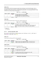
LED3 (EMU)
This LED lights when the target program is started from the debugger to indicate that the target system is
executing the target program. Also this LED lights when the target system is in power-off status or it is not
connected. In this case, the LED will go out by turning the target system on or by pressing the RESET/ START
switch after connecting the target system properly.
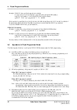
Table 3.3.1.1.3 LED3 Status
S1C17 S1C33 LED
status
Status
The target system is in power-off status.
The target system is not connected properly.
(red)
The target system is executing the user program.
(out)
Other
LED4 (DBG)
This LED indicates that the target S1C processor is placed in debug mode.
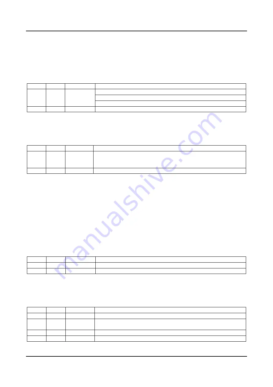
Table 3.3.1.1.4 LED4 Status
S1C17 S1C33 LED
status
Status
(green)
The target S1C processor is placed in debug mode.
Also this LED rights with LED3 before the initial connection between the
S5U1C17001H and the target S1C processor has been established.
(out)
Other
: Supported
– : Not supported
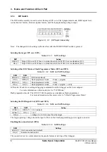
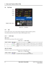
3.3.1.2
In Flash programmer mode
When the S5U1C17001H starts up in Flash programmer mode, LED2 lights in white (
), LED3 lights in
magenta (
), or LED4 lights in yellow (
).
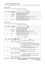
LED1 (CPU)
This LED indicates the target CPU selected using SW1.
Table 3.3.1.2.1 LED1 Status
S1C17 S1C33 LED
status
Status
–
(blue)
Mode for products with embedded S1C17xxx or S1C17 Core (C17)
–
(green)
Mode for products with embedded S1C33xxx or S1C33 Core (C33)
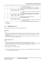
LED2 (ERASE)
This LED indicates a Flash erasing selection/operation status.
Table 3.3.1.2.2 LED2 Status
S1C17 S1C33 LED
status
Status
(white)
The Flash erasing function is selected.
(blinking
white)
The Flash memory is being erased.
(green)
The Flash erasing operation has completed normally. (OK)
(red)
A Flash erase error has occurred. (ERR)


