PhotoPC700
Chapter5 Adjustment
Rev. A
5-10
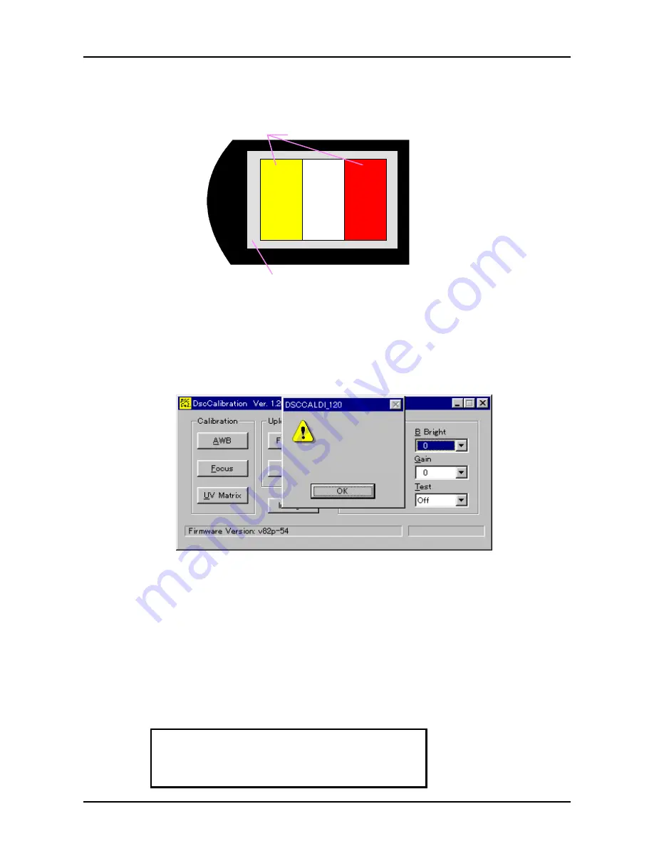
6. By selecting “Monitor” in the test buttons on the program, make sure that the camera lens is
capturing the color adjustment chart as it is shown below.
EPSON
Be sure that 3 colors for color adjustment chart
appears on the screen correctly.
Be sure that gray out-frame of
color adjustment chart appears.
Figure 5-9. Camera Angle Before Adjustment
7. After checking the camera angle as it is shown above, turn Off “Monitor” setting on the
adjustment program so that the image is not received on the LCD.
8. Press UV Matrix button.
9. Since the screen to confirm the selection appears, press Y(Yes).
10. The camera automatically shoots, and adjustment values appears on the screen.
ÒÓ ÊÞñïæõ Ïâðòéñ
ÒÓʾѺ®
ÒÓʾѮº®
ÒÓʾѯºª²
ÒÓʾѰº²µ
Figure 5-10. Condition of the Program After Adjustment is done
11. Check each adjustment value by following instructions. Each value range is listed below.
UVMAT0:
Check if the value is within the range or not.
UVMAT1:
If this adjustment value is below 128, check if that value is within the range
or not. If this adjustment value is more than 129, check if the value, which
this adjustment value minus 256 (this adj.value
−
256), is within the range or
not.
UVMAT2:
If this adjustment value is below 128, check if that value is within the range
or not. If this adjustment value is more than 129, check if the value which
this adjustment value minus 256 (this adj.value
−
256), is within the range or
not.
UVMAT3:
Check if the value is within the range or not.
UVMAT0 = 57
∼
157
UVMAT1 =
−
30
∼
30
UVMAT2 =
−
70
∼
−
19
UVMAT3 = 5
∼
105
Содержание PhotoPC700
Страница 1: ...6 59 0 18 EPSON PhotoPC 700 RORU 6WLOO LJLWDO DPHUD EPSON PhotoPC700 4009250 ...
Страница 5: ...REVISION STATUS Rev Date Page s Contents A 1998 05 12 All First release ...
Страница 7: ...MAINTENANCE APPENDIX 7 1 1 Circuit Diagrams 7 1 7 1 2 Location Diagrams 7 2 ...
Страница 8: ...PRODUCT DESCRIPTION 3 7 5 ...
Страница 51: ...203 200 150 151 PACKING MATERIALS FOR CP 600 PHOTO PC 700 01 02 03 04 ...


